
Posted by Dolf Broekaart
Table of contents
This blog shows how we performed a drop test for a Polyethylene 100 liter Fueltank containing fluid with SIMULIA Abaqus FEA Software. The goal of this analysis is to predict the possible material behaviour and failure that will lead to leakage.
This example involves a fluid-filled plastic tank falling from a height of roughly 15 meters onto a flat, rigid floor. The tank as shown in the pictures below is made of high-density polyethylene with a wall thickness of 5 mm everywhere. The tank is filled almost completely (about 90%) with water. A realistic simulation for the tank must account for both the exterior forces on the tank from the floor impact, as well as the interior forces of the water pushing against the walls of the tank. Resulting stresses and strains in the tank will be used to determine its structural feasibility.
How Do We Do This?
We will describe in this step by step approach how we performed this simulation.
1. Creating the Geometry
First we have modelled the tank. We have modelled this 100 liter tank in SolidWorks, created a midsurface geometry and saved the part. To prevent sloshing in the tank, we have modelled plate ribs with an opening on the bottom side so fluid can flow from one chamber to the other, and not fully extended to the top of the tank. See picture below.
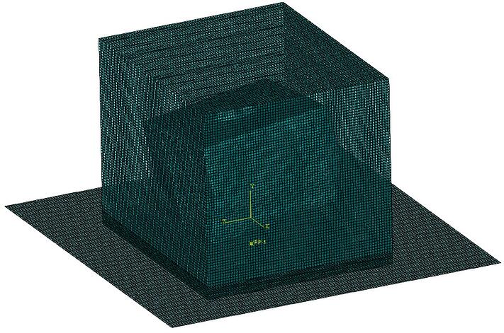
We have created a new assembly and imported the tank part. We positioned the tank on such a way that it impacts on a corner instead of full flat on the floor. After that, we created a new part in that assembly that represented the ground surface. After that we modelled the water with a horizon parallel to the ground. Since the tank is rotated, the water part is obviously also under an angle. We also created a box shaped Eulerian part. This Eulerian part represents the Eulerian domain, and should be sufficiently big to capture the necessary details.

We imported the parts into Abaqus with the SolidWorks Associative Interface and continue from there.
In Abaqus, the parts are now imported and instanced into the assembly. We defined the Eulerian part by right mouse click on the part and choose > Edit Part.
We selected 3D Eulerian to treat the Eulerian domain accordingly.
We have created sections for the Fluid, Tank and the Ground.
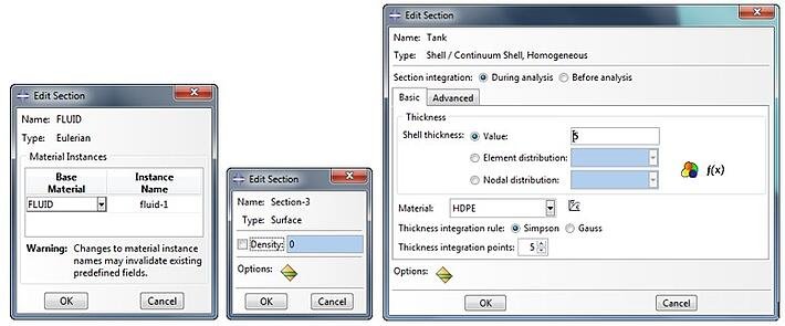
After that, the sections are applied to the Eulerian, Tank and Ground. Please be aware that we selected the Eulerian Box part that represents the domain. The actual water that we modelled will be used later on. So for the inner water part, no section is created nor applied.
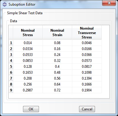
2. Adding the Material Properties
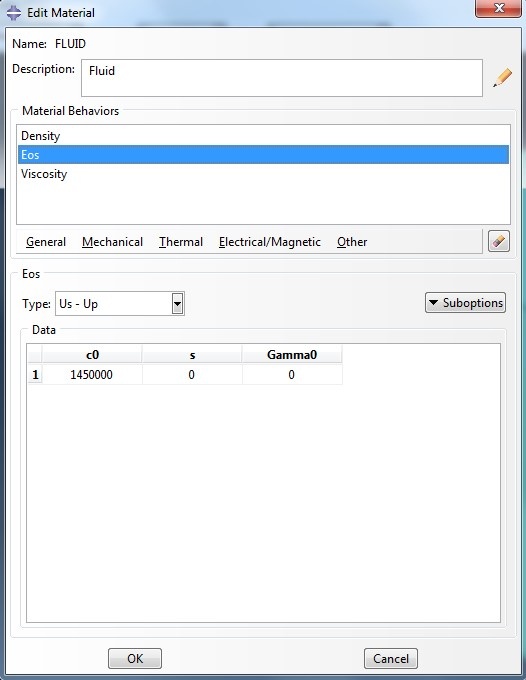
The tank is constructed of high-density polyethylene that follows an isotropic plastic hardening model. The water is treated as a nearly incompressible fluid.
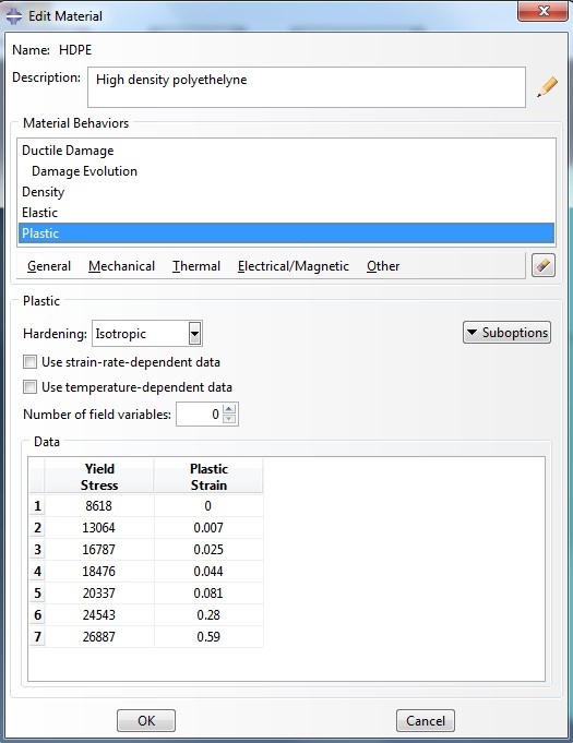
Damage is incorporated using a ductile damage definition. The high-density polyethylene has a density of 8.76 × 10⁻⁷ kg/mm3, Young's modulus of 903.114 N/mm2, and Poisson's ratio of 0.39.
The water has a density of 9.96 × 10⁻⁷ kg/mm3 and bulk modulus of 2.094 GPa.
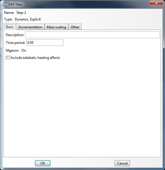
3. Creating the Explicit Step
For the loading step, we used a time period of 0.05
4. Mesh the Parts
We have meshed all the parts with a mesh size of 10 mm, with S4R elements for the Tank, SFM3D4R elements for the ground and EC3D8R elements for the Eulerian Domain
5. Interaction
For the interaction we have used general contact with default Abaqus settings.
In order to account for the position of the water within the Eulerian domain we used the Volume Fraction Tool.
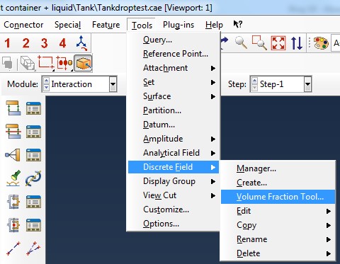
You first need to select the Eulerian Domain, and then the reference part. In this case the reference part is the water shape that we modelled. The Volume Fraction tool creates the discrete field for you. Please be aware that each time if you remesh any of your parts, the discrete field needs to be regenerated with the volume fraction tool.
6. Loads & Fixtures
We applied a gravity load of -9800 in the Y-direction for the Eulerian domain and we also applied a separate gravity load of -9800 to the tank. For the ground we fixed all displacements and rotations.
Falling height for this analysis is 15 meters. We are not interested in the falling in the air bit, so we positioned the parts on the location just before impact and applied a velocity to the bodies that is equal to the impact velocity.
This can be calculated by:
![]()
So this would give you Velocity = 17,15 m/s
The initial velocities (in mm/s) for both Eulerian Domain and the Tank are created as predefined fields.

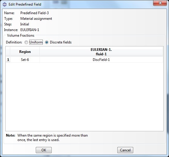
After this, the last predefined field needs to be created where we will use the Other > Material assignment, from the discrete field that we generated with the Volume Fraction Tool.
7. Create & Submit the Job
We have created the job running on 4-cpu’s and submitted the job. It takes around 3-hours to run this Analysis with an evenly spaced time interval of 100 for the Field Output Variables. Don’t forget to create a new Field Output Variable that requests for the EVF, Void/Material volume fraction in elements (eulerian only). Found under Volume/Thickness/Coordinates before you submit the job.
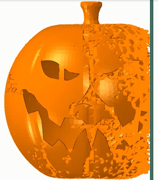
8. Final Results
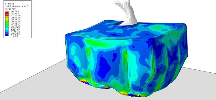
(Stress in the tank in kPa)
VIDEO of the Animated results
Are you interested in simulating drop tests, impact test with or without fluids, soils or particles inside?
Use our specialism and get in contact with us.


TECHNIA Simulation provides top tier FEA, Non-linear, and Advanced Simulation Software, Training, and Consultancy. Our dedicated team of more than 65 Simulation experts across 16 countries advise and support your innovation with a wealth of specialist knowledge and experience.
About TECHNIA- Related news and articles straight to your inbox
- Hints, tips & how-tos
- Thought leadership articles

Helping you find the information you’re looking for. Discover webinars, events, FAQ's, case studies and tutorials.
VIEW HUB