
Posted by Christine Obbink-Huizer
Categories
Abaqus Crack ModellingTable of contents
In many cases it is important to know whether a crack will propagate. Simulating this requires special techniques, especially for sharp cracks. In a perfectly sharp crack, loading is applied to a single point, causing a singularity with an infinitely large stress. In a simulation it is not possible to obtain an infinitely large stress. The loading will be localised in a single element and therefore the results will depend strongly on the mesh, which is unwanted. In the real world, perfectly sharp cracks do not exist; a crack will always have a finite thickness. Because this thickness is very small, it is difficult to measure and take into account numerically. Because the stress at a crack depends strongly on the mesh/thickness of the crack, looking at stress to determine whether a crack will propagate does not work well. Instead, other measures are used. One of these is the stress intensity factor (K), which describes how quickly the stress increases towards the crack, assuming a linear elastic material. Another is the J-integral, which describes how much strain energy is released per unit fracture surface area. Abaqus can calculate such outcomes for a crack, which can then be compared to critical values to determine whether or not a crack will propagate. In this blog I will explain how to set up a simulation to determine the stress intensity factor or J-integral.
Partitioning Crack
There are several things to pay attention to when modelling a crack. First of all, the crack itself needs to be simulated. A partition is made representing the crack.
In this case, the face is partitioned, and the Partition Cell: Extrude/Sweep Edges tool is used to extrude the partition on the face.

Alternatively, a separate shell part can be made that represents the crack. Using the Merge/Cut Instances feature in the assembly module a part containing a partition for the crack can be made.
Creating a Seam
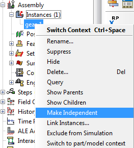
When simply creating a partition to represent the crack, the elements on both sides of the partition will be connected to each other: they will share nodes. For a crack, this is unwanted. Separate nodes on elements on each side of the crack can be created by defining a seam. This in only possible on independent instances. In the interaction module, under special => crack => Assign Seam… a partitioned edge or face can be chosen that will act as seam.


Defining the Crack
To be able to request crack-related output, a crack needs to be defined. This is done in the Interaction module, using Special => Crack => Create, or by double clicking ‘Cracks’ in the model tree, under ‘Assembly’, ‘Engineering Features’. In the ‘Create Crack’ dialog box that appears the type ‘Contour Integral’ is selected.


Crack Front and Crack Tip/Line
The crack front is then selected. Contour integrals, such as the J-integral that we will calculate here, are calculated for layers of elements around the crack. The crack front determines the first layer of elements to be used. For this sharp crack, the edge representing the crack tip can simply be used, it is not necessary to define the crack tip seperately then. For blunt cracks, the crack front is a face and the crack tip/crack line needs to be defined seperately.
Crack Extension Direction
After the location of the crack is defined, the crack extension direction is specified, either as normal to the crack plane or by specifying q vectors. The last option is used here and a q vector in the direction of the crack is specified. When the extension direction is defined using q vectors on geometry, only one direction can be specified. In this case that is no problem, because the crack extension direction is the same for all nodes along the crack line. When different q vectors at different nodes are required, this is only possible by using an orphan mesh.
Symmetry
In the ‘edit crack’ window that opens when the q vector is defined, there is an option to specify that the crack is on a symmetry plane. If this option is used, no seam needs to be defined. Instead, no symmetry boundary conditions are applied where the crack is located, allowing it to open.
Prescribing a Singularity
In the ‘singularity’ tab, a singularity can be included in the mesh. This helps to describe the stress and strain field at the crack. Midside nodes can be moved towards the crack tip and hexahedral elements can be collapsed to wedges with multiple nodes at each location at the crack tip. The nodes at the same location at the crack tip can either be contrained to move together as a single node, or they can behave as duplicate nodes. The relationship between strain (ε) and distance to the singularity (r) depends on these settings. For linear elasticity, ε ∝ 1√r.
This can be modelled using a midside node parameter of 0.25 and collapsed element sides with nodes constrained to move together.
Mesh
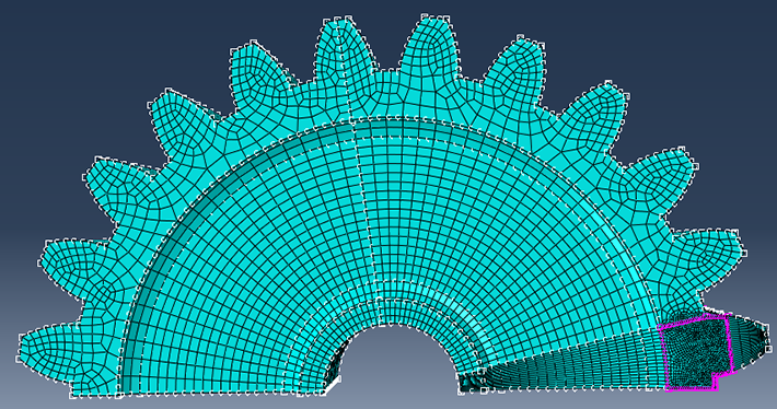
Because the contour integrals are calculated for layers of elements around the crack front, a mesh with layers of elements in rings around the crack tip, a spider web like mesh, is beneficial. To create such a mesh, an additional partition is made, corresponding to a circle centred around the crack tip. The spider web will be inside this circle. A hex-dominated swept meshing technique is assigned within the newly partitioned cell.

If the sweep path is along the edge of the circle, wedge elements will be created at the centre of the circle. If this is used along with a singularity with collapsed element sides, collapsed elements will be used instead of wedge elements. For more complex geometries where the sweep path is not along the edge of the circle, it can be beneficial to partition an inner and an outer circle and define a single layer of wedge elements in the inner circle.
Mesh Seeding
A locally refined mesh is created by specifying the amount of elements along the circular edge and along the crack. It is recommended to use at least 16 elements around a complete circle. Each ring of elements along the crack corresponds to a contour integral. The first 2 contour integrals are commonly neglected, because the crack tip is so close it can lead to unwanted effects. Contour integrals close to for example boundaries can be influenced by other things than the crack. Therefore, contour integrals 3-5, close to the crack, are commonly used for evaluation. Quadratic elements are used to aid in capturing stress concentrations.
Checking Mesh
When the instance is meshed and the part is colour coded based on the element types, it is clear that while the elements at the crack tip are wedge shaped, the hexahedral C3D20R element type is used. 
Querying the elements shows repeated nodes, as expected because the ‘collapsed element side, single node’ option was chosen. Querying elements on both sides of the crack, shows that the elements do not share nodes.
Requesting Output
When the crack is defined and a mesh is created, output can be requested. History output specifically for cracks can be requested, by selecting ‘Crack’ as domain and then selecting the crack of interest. The number of contours (number of layers around crack front for which the integral is calculated) and the type of integral needs to be specified. It is not possible to request more than one type of integral in a single history output, but it is possible to request them in separate history outputs.

Defining the Rest of the Simulation
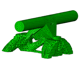
Of course just specifying a crack does not allow us to run a simulation. Material properties, loads and boundary conditions need to be applied as well. In this case, a linear elastic steel is used and the gear is fully constrained in the centre, while a force is applied to separate both teeth and open the crack.
Results

Using a deformation scale factor of 100, and opened crack is visible. Many history outputs were created. For each contour at each node of the crack line, there is a history output. Using the ‘filter’ option on the history output is useful to select contours for a specific node. Node sets are automatically created to show which history outputs corresponds to which node. For one of the nodes, the given values for the J-integral are as shown in the image. Be aware that the scale does not start at 0. The bigger markers are for the first two contours. If a reasonable value is to be find, all contours should be the same. For the contours other than the commonly neglected first and second contour, this is indeed the case. The calculated energy release rate can then be compared to the materials fracture energy to determine whether the crack will propagate.

Are you interested to investigate if cracks will cause a potetial failure?


TECHNIA Simulation provides top tier FEA, Non-linear, and Advanced Simulation Software, Training, and Consultancy. Our dedicated team of more than 65 Simulation experts across 16 countries advise and support your innovation with a wealth of specialist knowledge and experience.
About TECHNIA- Related news and articles straight to your inbox
- Hints, tips & how-tos
- Thought leadership articles

Helping you find the information you’re looking for. Discover webinars, events, FAQ's, case studies and tutorials.
VIEW HUB