

Posted by Nikolaos Mavrodontis
Categories
Stress-StrainTable of contents
This blog focuses on the difference between Engineering Stress-Strain and True Stress-Strain. Furthermore we will explain how to convert Engineering Stress-Strain to True Stress Strain from within Abaqus. Abaqus offers many possibilities with respect to material modelling. Apart from including elastic properties, also various options are offered for modelling of plasticity. Usually for accurately modelling materials, relevant testing is conducted.
Different engineering materials exhibit different behaviors/trends under the same loading regime.
More traditional engineering materials such as concrete under tension, glass metals and alloys exhibit adequately linear stress-strain relations until the onset of yield (point up to which materials recover their original shape upon load removal) whereas other more modern materials (e.g. rubbers, polymer) exhibit non-linear stress-strain relations directly upon being loaded externally.
Additionally with respect to their behavior in the plastic region (region in which even after load removal some permanent deformations shall remain), different stress-strain trends are noted. Brittle materials usually fracture(fail) shortly after yielding-or even at yield points- whereas alloys and many steels can extensively deform plastically before failure. The characteristics of each material should of course be chosen based on the application and design requirements.
In order to model material behaviors, usually stress-strain curves are produced as a result of testing. The type of test conducted should be relevant to the type of loading that the material will endure while in service.
A relevant test that focuses on stress-strain curve output is the uniaxial tension test. A typical stress-strain of a ductile steel is shown in the figure below. The stress and strain shown in this graph are called engineering stress and engineering strain respectfully. They correlate the current state of the steel specimen with its original undeformed natural state (through initial cross section and initial length).
The Yield point can be clearly seen as well as the plastic region and fracture point (when the specimen breaks).
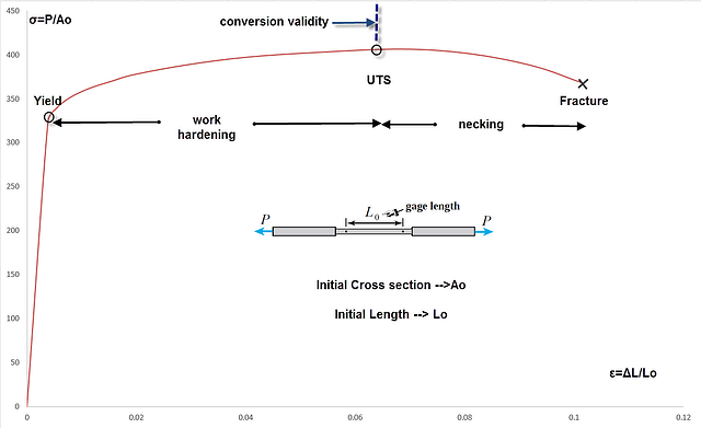
Within the plastic region two sub-regions are distinguished, the work hardening region and the necking region. These two regions are separated by the Ultimate Tensile Strength (UTS) point of the material, representing the maximum tension stress that the specimen can withstand.
In Abaqus (as in most fea software) the relevant stress-strain data must be input as true stress and true strain data (correlating the current deformed state of the material with the history of previously performed states and not initial undeformed ones).
Analytical equations do exist for converting these information. Additionally Abaqus offers extra tools for automating these conversions as well as for calculating certain material properties directly from test data sets.
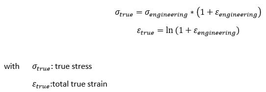
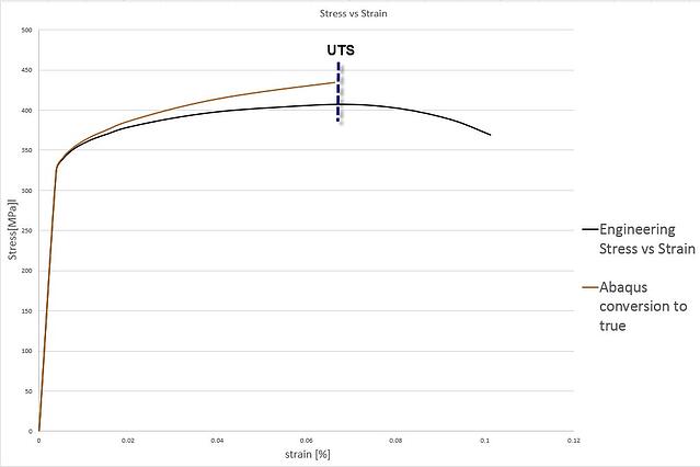
The analytical equations for converting engineering stress/strain to true stress/strain can only be used until the UTS point (conversion validity shown in Figure). The necking phenomenon that follows prohibits the use of these equations.
The analytical equations for converting engineering stress-strain to true stress-strain are given below:
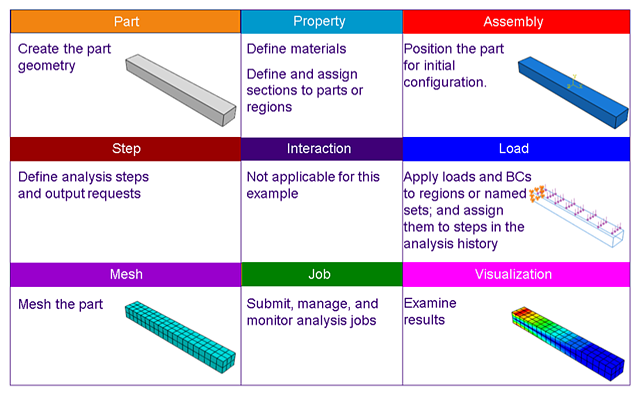
In Abaqus the following actions are required for converting engineering data to true data, given that the engineering stress-strain data is provided as a *.txt file.
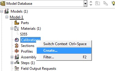
1. Create a Material Calibration
2. Create a New Data Set That Will Be Imported Next
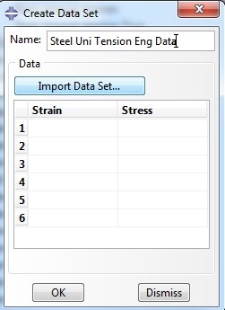
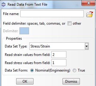
3. Read Data From Textfile
Browse for and import the data set (*.txt file) while appointing right fields on stress-strain information and selecting the nature of the data set (in our case nominal –engineering- data)
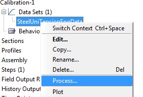
4. Process Dataset
After importing the engineering data, Abaqus plots the data points. Next we right click on the respectful data set and select process.
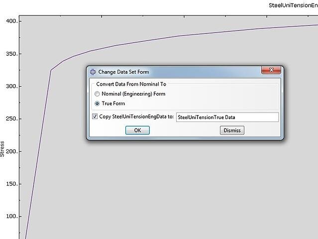
5. Convert Engineering Data to True Data
We choose convert as operation (convert from engineering data to true data) and Abaqus creates the converted data set after choosing the settings shown to the right. We can also plot this information in Abaqus.
The two stress-strain curves (engineering and true) are shown in the figure below:
Important note 1:
Since emphasis in this blog is given to presenting the analytical equations mentioned above, it is reminded once again that these are valid up to the UTS point. This is why the data conversion within Abaqus is shown up till this point. The full conversion of relevant data until material fracture can easily be handled by Abaqus given that during the relevant tension test, the instantaneous cross sectional area of the specimen is measured so as to acquire a meaningful engineering stress-strain relationship from UTS until fracture. This procedure in Abaqus is exactly the same as already described.
Important note 2:
In order to include plasticity within Abaqus, the stress-strain points past yield, must be input in the form of true stress and logarithmic plastic strain. The logarithmic plastic strain required by Abaqus can be calculated with the equation given below:
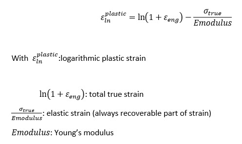
The first data point must always correspond to the yield point (yield stress, logarithmic plastic strain=0 ) and the subsequent strains can be calculated from the equation provided above.
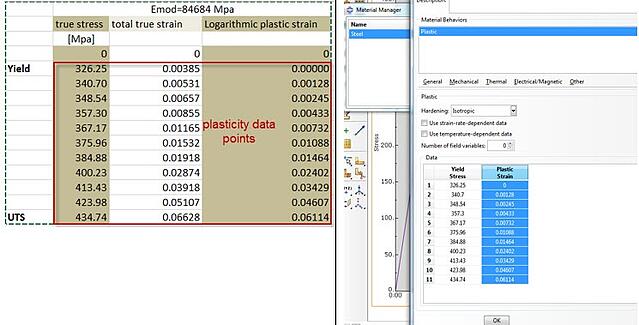
For the exemplary stress-strain data , the following information must be input in Abaqus from implementing plasticity (enclosed in red color):
In the following link you can download the excelsheet which you can also use to do the conversion.
Conversion Engineering Stress-Strain to True Stress-Strain
Are you finding challenges in modelling the necessary material behaviour for you engineering challenge..?


TECHNIA Simulation provides top tier FEA, Non-linear, and Advanced Simulation Software, Training, and Consultancy. Our dedicated team of more than 65 Simulation experts across 16 countries advise and support your innovation with a wealth of specialist knowledge and experience.
About TECHNIA- Related news and articles straight to your inbox
- Hints, tips & how-tos
- Thought leadership articles

Helping you find the information you’re looking for. Discover webinars, events, FAQ's, case studies and tutorials.
VIEW HUB