

Posted by Christine Obbink-Huizer
Table of contents
Geometry is often drawn in 3D, also when it is axisymmetric. The analysis will be much faster when making use of the axisymmetry. In such cases, we need to get an axisymmetric cross-section out of a 3D model. In this blog I will show a way to do this with Abaqus. The main idea is to create a sketch on a cross-section of the part and project the relevant edges to this sketch. This sketch is saved and used to create a new axisymmetric part. This isn't the only way of doing it, but at least it gives an idea.
Importing the Original Geometry
First of all, the original (3D) geometry is imported. This can be done via file --> import --> part. In this case I’ll import a .stp file corresponding to a valve geometry so the file filter is set to STEP. The file name is selected. In the Create Part from STEP file dialog box that appears, the to be created part is given a name, in this case valve_3D (Figure 1).
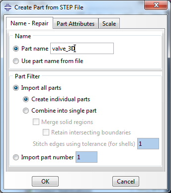
Figure 1: Create Part from STEP file dialog box.
A 3D part is then created, this appears in the model tree (Figure 2).
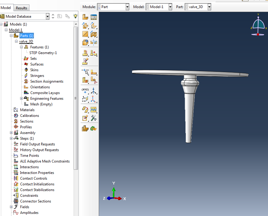
Figure 2: The imported geometry.
Create Axis and Plane
Next, we will create a plane passing through the geometry, so that the geometry of the part on the plane matches the cross-section we want to model. There are different ways to do this. One is to first create a datum axis corresponding to the axis of symmetry. This can easily be done using the Create Datum Axis: 3 points on a circle option. Select three vertices on a circle (so three points that correspond to the same point in the axisymmetric representation), e.g. the ones shown in Figure 3.
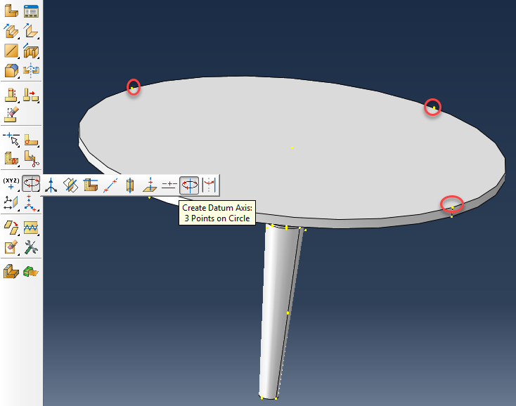
Figure 3: Create symmetry axis.
This axis can be used to create a plane, via the Create Datum Plane: Line and Point option. Select the newly created axis as line and any point on the geometry not on the line as point.
Create Cut to Obtain Cross-section
Half of the model will be removed, so that the cross-section becomes visible. This can be done via the Create Cut: Extrude option. Select the created datum plane as plane for the extruded cut, and the axis as edge or axis that will appear vertical and on the right. Draw a rectangle around the complete geometry (Figure 4).
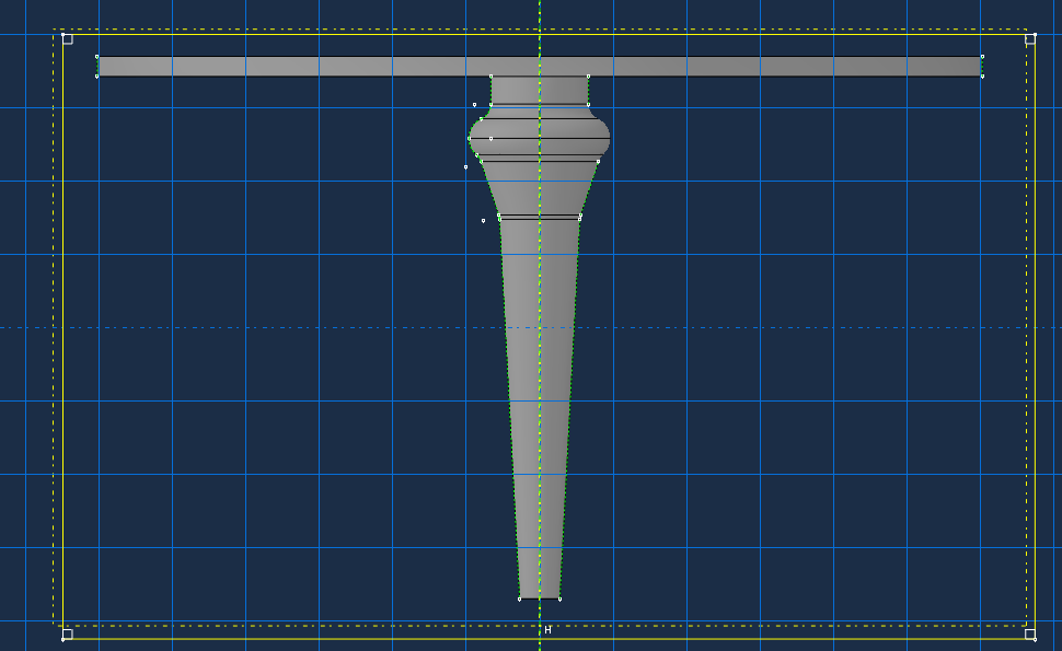
Figure 4: Sketch of what is to be cut.
Use the Through All end condition, to cut off half of the geometry.
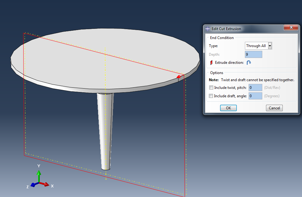
Figure 5: Cutting of half of the geometry.
Create and Save Sketch
The cross-section of interest is now visible (Figure 6), but it can’t be used directly.
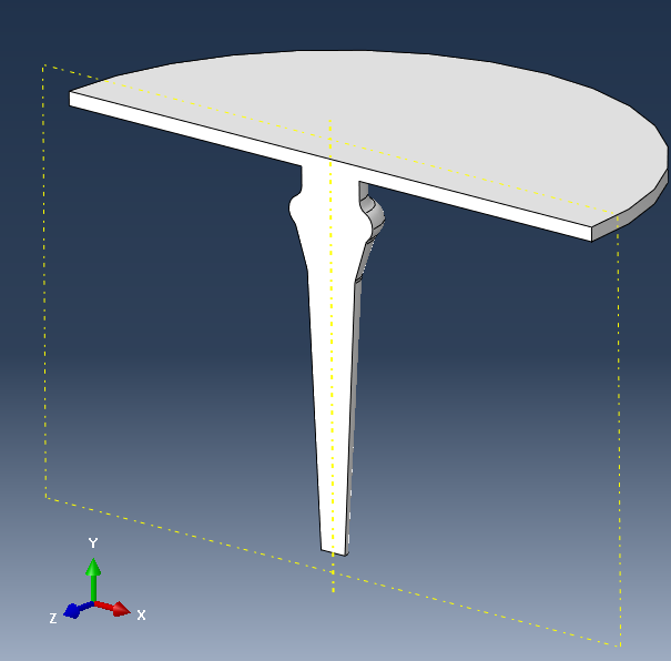
Figure 6: Geometry after making cut.
We will save it in a sketch. A simple way to do this, is to use any tool that allows you to create a sketch on the existing geometry, such as the Partition Face: Sketch tool. Select the cross-sectional face as faces to partition and the axis as edge or axis that will appear vertical and on the right.
Use the Project Edges tool to transfer the existing edges to the sketch (Figure 7).
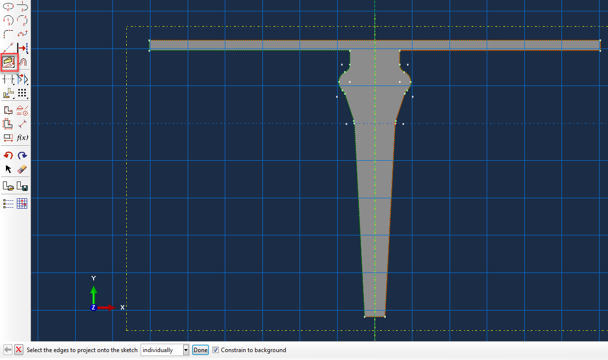
Figure 7: Projecting edges on sketch.
In this case, we need only half of the geometry. The auto-trim option and Create Lines: Connected tools are used to cut off the half of the geometry not needed and close it along the axis. If the axis of symmetry is not part of the geometry, it makes sense to include a construction line for it.
Once the sketch is finished, it can be saved using the Save Sketch As tool (Figure 8).
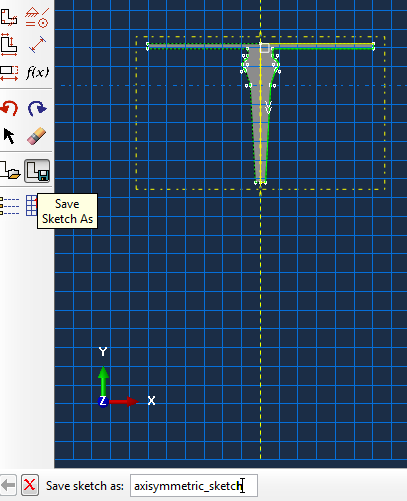
Figure 8: Saving sketch.
The sketch is now visible in the model tree (Figure 9).
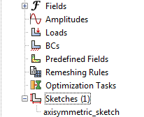
Figure 9: Sketch shown in model tree.
The tool used to create the sketch (such as partition face) can now be closed. It is not necessary to save the changes, because the only reason for using the tool, was to create a sketch that is already saved. However, if an edge was accidentally forgotten it will be possible to modify the sketch in the feature created by the tool and save it again. This option is not available when using the tool is cancelled.
Create New Axisymmetric Part
The next step is to create a new axisymmetric part. Go to the Part module, select Part à Create and select Axisymmetric as modelling space (Figure 10).
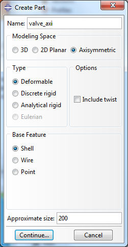
Figure 10: Creating a new axisymmetric part.
The sketch module is now opened. Select the Add Sketch tool (Figure 11) and choose the sketch that was just saved.

Figure 11: Add sketch tool.
You now have the option to reposition entities. If the sketch is upside down, not in the correct position, etc. the entire sketch can be translated, rotated, mirrored or scaled. Multiple repositioning steps are possible as well. In this example, repositioning is not necessary. Other geometrical changes can be made if necessary and the final sketch can be confirmed. With this we have obtained an axisymmetric geometry (Figure 12).
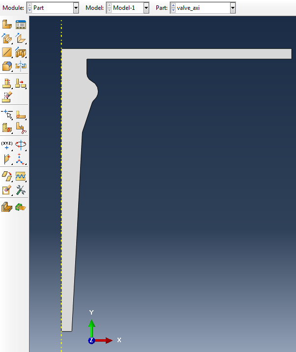
Figure 12: Final axisymmetric geometry.
Axisymmetric Visualization
With this axisymmetric geometry, the analysis can be run. Running an analysis with axisymmetric elements is much faster than running it with 3D solid elements. However, you may want to show results on 3D geometry. This is possible in Abaqus’ visualisation module. Go to viewà odb display options and then the Sweep/Extrude tab. Here it is possible to sweep the elements over a specified angle and also to select the number of segments. More segments will give a ‘rounder’ shape. The results don’t change when using this option, but it may be easier to convince others of using an axisymmetric approach if they see more than just a cross-section.
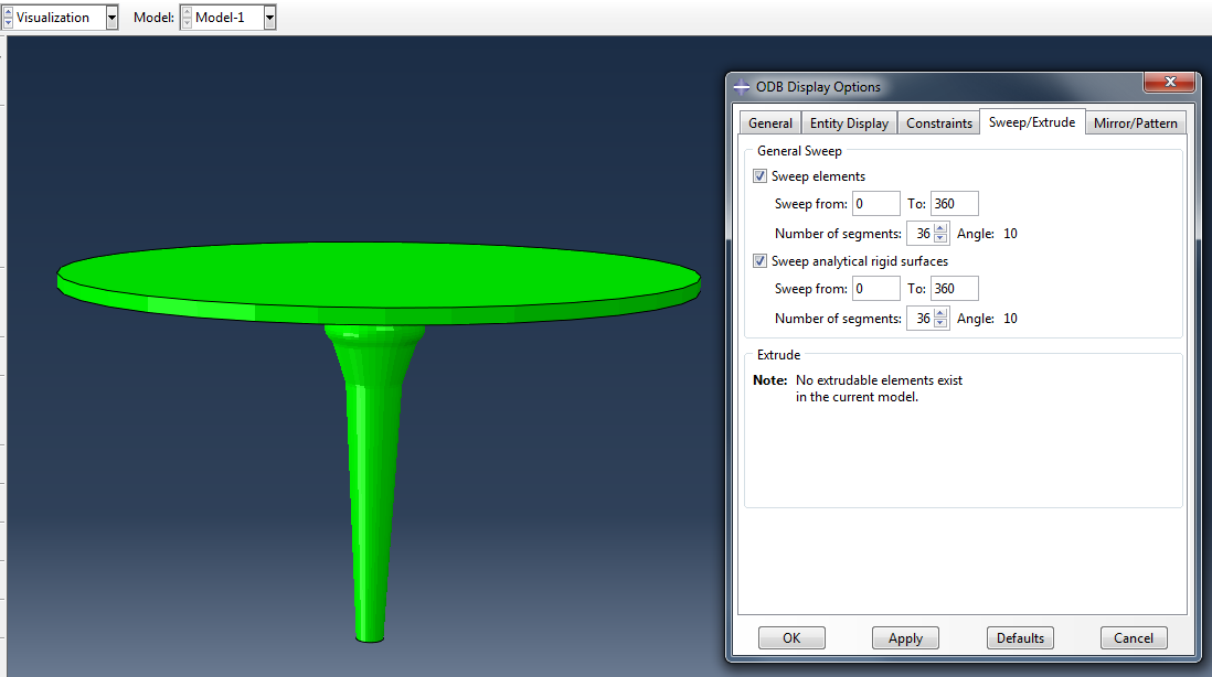 Figure 13: 3D visualisation of axisymmetric model.


TECHNIA Simulation provides top tier FEA, Non-linear, and Advanced Simulation Software, Training, and Consultancy. Our dedicated team of more than 65 Simulation experts across 16 countries advise and support your innovation with a wealth of specialist knowledge and experience.
About TECHNIA- Related news and articles straight to your inbox
- Hints, tips & how-tos
- Thought leadership articles

Helping you find the information you’re looking for. Discover webinars, events, FAQ's, case studies and tutorials.
VIEW HUB