
Posted by Christine Obbink-Huizer
Table of contents
In this blog we'll simulate a sheet metal forming process called deep drawing, with SIMULIA Abaqus Software. It can be challenging to design a deep drawing product and the tools to create it, because many potential issues are not observed until the first prototype is produced. Simulations can help determine whether a design suffices, without actually having to create costly tools or do time consuming tests. Multiple design iterations can easily be investigated.
Introduction
During deep drawing, sheet metal is transformed into a 'deep' shape, such as a cup. This is achieved by using a punch that pushes the sheet metal blank into a die, to form the final shape. A holder is used so the sheet outside the punch region stays flat (Figure 1).
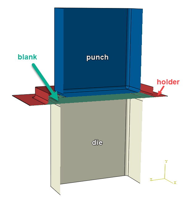
Figure 1: Deep drawing set-up. The blank is in between the die and the holder. The die does not move. The holder exerts a force on the blank and die. The punch moves downwards, and as this happens it deforms the blank.
An important aspect here is that the material is drawn in from the edges and therefore slides in between the holder and the die. The outer edges of the blank are not clamped, but move inwards. The deep shape is mainly created by bending and reorienting the material, rather than stretching it.
Example problem - first iteration
As an example, we'll take a look at a rectangular pan. After some more postprocessing, this could be used as sink. We'll start with the set-up as shown in Figure 1. The die is fully restrained. A constant force pushes the holder down. A downwards displacement is applied to the punch, all other degrees of freedom are restrained. All tools are considered rigid. Elastic-plastic steel material properties are used for the blank. Contact is included with a friction coefficient of 0.1.
This is what happens:
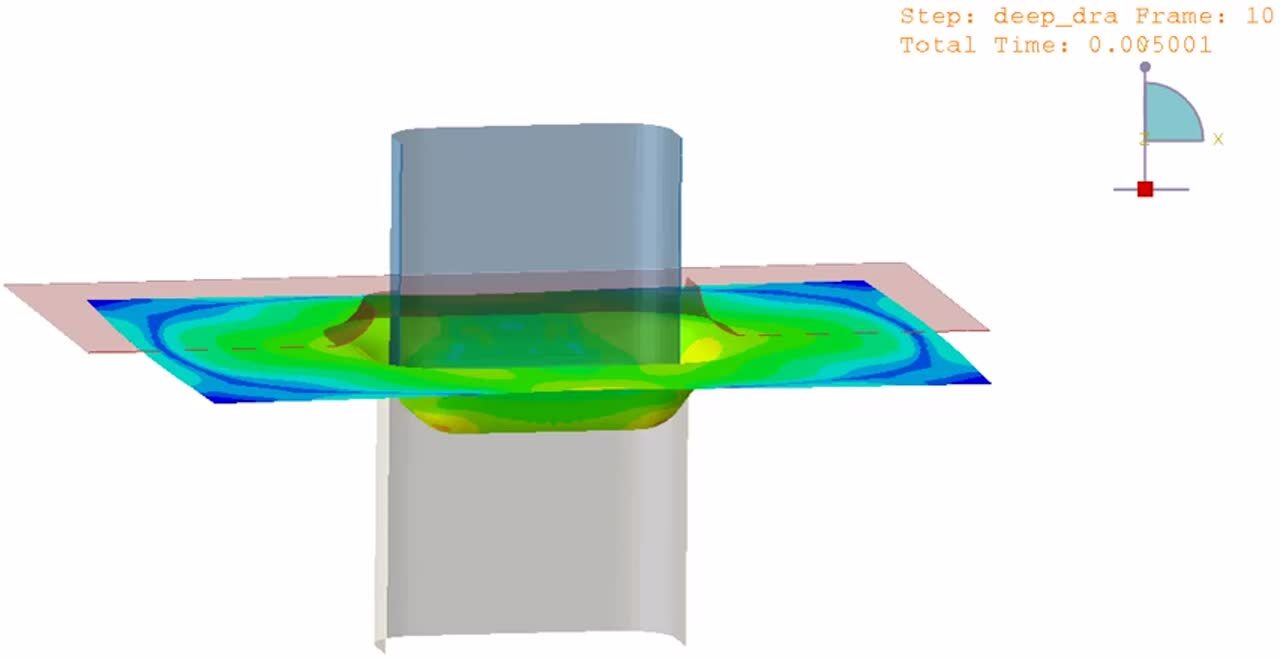
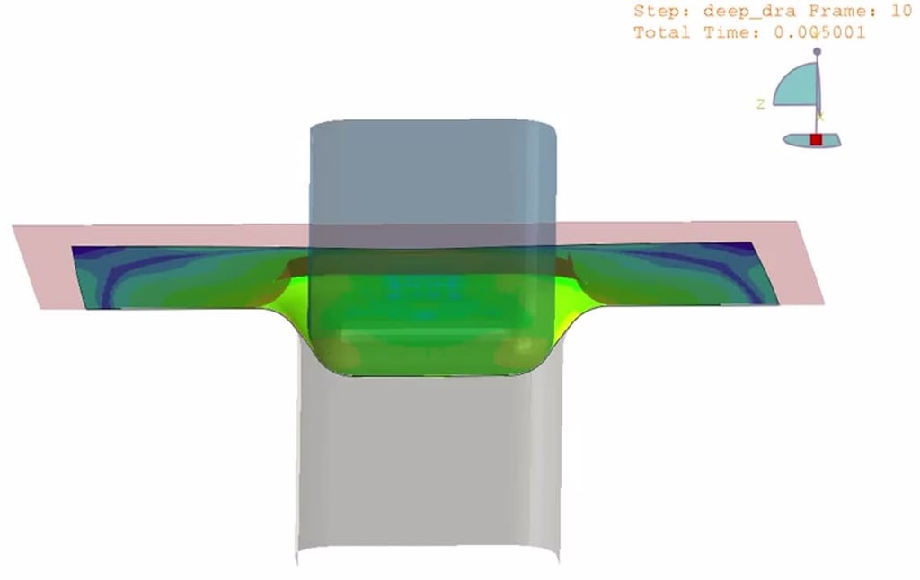
Video 1: Deep drawing process with first design. A cross-section of the transparent tools is shown, along with the full blank. Colors indicated von Mises stresses.
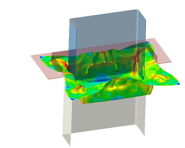
Figure 2: Final state of analysis with the first design.
The analysis shows that the material wrinkles in the corners. Furthermore, the edge of the blank is released from the holder and starts wrinkling at the middle of the edge. This is unwanted.
Second iteration: smaller hole in holder and larger blank
To get rid of the wrinkling in the previous attempt, the blank has to be flattened between the die and the holder over a larger region. The distance between the punch and the holder will therefore be reduced, leading to a smaller opening in the holder. Furthermore, the size of the blank, die and holder will be increased, so the blank will not slip from underneath the holder as easily. The amount of displacement is also increased, to have deeper drawing. This is what happens in this updated case:
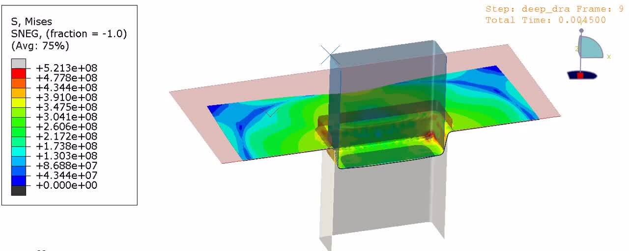
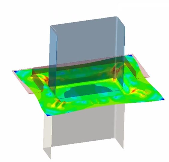
Video 2: Deep drawing process with second design, with a larger holder and blank. A cross-section of the transparent tools is shown, along with the non-transparent blank. Colors indicated von Mises stresses.
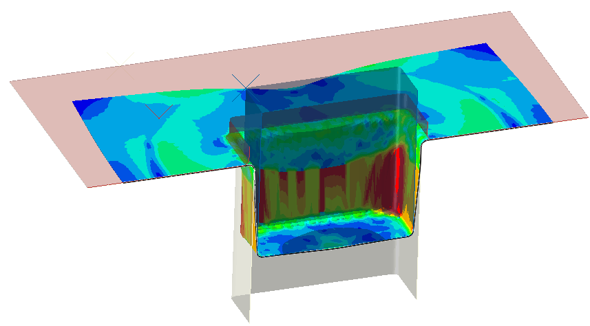
Figure 3: Final state for the analysis with the second design.
As intended, there is no wrinkling in this case. However, there is a new issue: the stresses are very much localized. In fact, the red/orange/yellow region that can be seen in this image, consists of a single element in vertical direction that is plastically deforming a lot. Though this analysis did not include damage, I think it is fair to assume this would lead to so much local thinning, that the product will not be usable. Another design iteration is needed.
Third iteration: increase radii
In the previous video we see that initially the sheet metal slides (as intended) but after rounding the curve, it starts elongating, rather than being drawn downwards. The rather small radii in the design will make flow of material more difficult; increasing them may improve results. The third iteration, with larger radii, gives these results:

Video 3: Deep drawing process with third design. A cross-section of the transparent tools is shown, along with the non-transparent blank. Colors indicated von Mises stresses.
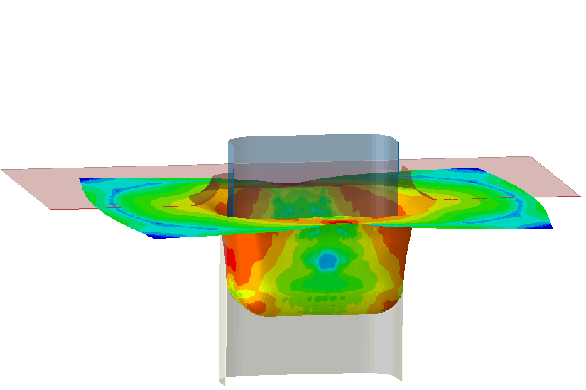
Figure 4: Final state for the analysis with the third design.
In this case, there is no wrinkling and no excessive local deformation as intended.
Bonus iteration: the effect of friction
While working on this blog, I varied different things to see their effect, including the friction coefficient. In all the analyses shown the same friction coefficient of 0.1 was used throughout the model. If the coefficient of friction is increased to 0.15 we get the following results:
Video 4: Deep drawing process with third design with increased friction coefficient. A cross-section of the transparent tools is shown, along with the non-transparent blank. Colors indicated von Mises stresses.
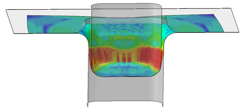
Figure 4: Final state of analysis with third design using an increased friction coefficient of 0.15
Though the geometry is the same as before, we get local stresses; again a single layer of elements takes most of the deformation. This shows the important impact lubrication can have.
Conclusion
With these examples I have shown that the deep drawing process can be simulated; not only when everything goes right, but also when unwanted effects occur. Further design improvements may be possible; the radius may be larger the necessary now, the blank size may not be optimum, etc. Because these analyses are fast (less than 10 minutes a piece on a single core) it is feasible to go through many iterations. By performing simulations in an early stage, the first prototype created can avoid some of the issues you may otherwise have.
Is your deep drawing process not behaving as it should? Or are you in the design stage, and do you want to your design to be first time right? Click below to share your challenge with us.


TECHNIA Simulation provides top tier FEA, Non-linear, and Advanced Simulation Software, Training, and Consultancy. Our dedicated team of more than 65 Simulation experts across 16 countries advise and support your innovation with a wealth of specialist knowledge and experience.
About TECHNIA- Related news and articles straight to your inbox
- Hints, tips & how-tos
- Thought leadership articles

Helping you find the information you’re looking for. Discover webinars, events, FAQ's, case studies and tutorials.
VIEW HUB