
Posted by Christine Obbink-Huizer
Categories
AbaqusTable of contents
In this blog, we will explain and show the different methods Abaqus has to treat an initial overlap of contact surfaces, with an axisymmetric O-ring as example.

Figure 1: cross-section of O-ring set-up used as example.
Reasons for Initial Overclosures
When working on contact problems, contacting surfaces can overlap at the start of the analysis; in this case there is an initial overclosure or penetration.
This can occur due to different reasons: the CAD modelling can be poor leading to overlaps between parts. This is unintended.
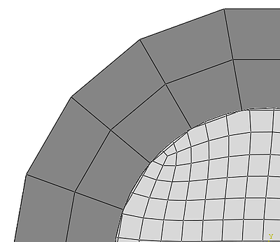
Initial overlap can also occur due to discretization errors. If two round, touching geometries with the same radius are discretized with a different element size, they will deviate from the original round shape in a different way (see Figure 2). This is also unintended.

Figure 2:
A third reason for initial overlap, is modelling of an interference fit. In this case the undeformed parts penetrate, because in practice they are deformed when placed in their initial position. This is the case with the O-ring, that will be deformed to fit in its initial position. In this case the overlap is intended, and it should be resolved in such a way that there are stresses and strains when the parts are in contact.
Ways of Solving Initial Overclosures
There are two main ways of solving initial overclosures in Abaqus: with strain-free adjustments or with interference fits.
Strain-free Adjustments
With strain-free adjustments, the nodes on the slave are moved in such a way that the overclosure is removed, without stress or strain occurring. This is suitable for unintended overlaps. The nodes are already moved at time point 0 of the first analysis step, so the undeformed mesh is changed. Especially for large overlaps, this can give distorted elements.
Interference Fits
When the overlap is treated as an interference fit, stresses and strains do occur when moving the nodes to a non-overlapping position. This is suitable for intended overlaps. At time point 0 of the first analysis steps the parts are in their originally specified positions and the overlap is solved during the first increment or during the first step of the analysis.
Specifying the Different Options in Abaqus
Whether initial overclosures are solved with strain-free adjustments or with interference fits by default, depends on whether general contact, or contact pairs are used. I will show how to set the different options and what the result is in the model of an O-ring.
General Contact
When using general contact, small overclosures are treated with strain-free adjustments by default. Abaqus chooses a master and slave surface itself, and a limiting value to determine what a small overclosure is. Overclosures bigger than this cut-off, are not adjusted.

Figure 3: general contact with default settings.
In the example, only one node is adjusted, because the other overclosures are too big. The cut-off value can be changed, by defining and specifying a contact initialization. In the ‘edit interaction’ dialog box for the general contact, Initialization assignments can be specified. By clicking on the icon indicated in Figure 4, a contact initialization can be created. Here the cut-off value to determine when an overclosure is so big that it can be ignored can be specified. Small gaps can be closed by specifying a non-zero value for Ignore initial openings greater than:

Figure 4: creating a contact initialization.
Click on the pencil icon behind Initialization assignments in the Edit Interaction dialog box to assign the newly created contact initialization to a surface pair. Select the required surfaces and the contact initialization assignment and press the button indicated in Figure 5 to create the assignment. This can be done for more than one set of surfaces, as required.

Figure 5: assigning a contact initialization to a pair of surfaces.
In this example, two sets of surfaces were defined, one for the contact on each side of the O-ring. The result is shown in Figure 6. Note that a coarse mesh was used. If more than one element in the slave overlaps the master, the elements will turn inside out, making them unusable for analysis. The model is stress and strain free in the image shown.

Figure 6: General contact, increased cut-off for ignored overclosures.
It is possible to specify that an initial overlap should be treated as interference fit for specified contacting surfaces using general contact. This is done with a contact initialization, similar to the way the offset for ignored overclosures was changed. When selecting Treat as interference fits for a pair of surfaces, the overclosure will be removed gradually during the first step, resulting in stresses and strains in the deformed parts (Figure 7).

Figure 7: General contact, specifying interference fit
Contact Pairs
When using contact pairs, overclosures are treated with interference fits by default, with the interference being solved in the first increment. With the mesh shown previously, the results after the first increment are similar to those with general contact and an interference fit.
When the diameter of the O-ring is reduced (Figure 8), Abaqus can no longer solve the interference fit in one increment (the default).

Figure 8: O-ring with reduced diameter.
In cases such as this, it is possible to gradually solve the overclosure during the first step. This is done by editing the interaction in the first analysis step and clicking on options: Interference Fit (Figure 9). It is important to select the first general analysis step (and not e.g. the initial step) as active step when defining an interference fit, because otherwise the required option will be grayed out.

Figure 9: Changing interference fit settings.
In the Interference Fit Options dialog box, the default setting is no allowable interference. In this case, the overclosures will be resolved in the first increment. The second option Gradually remove slave node overclosure during the step will be used here, with Automatic shrink fit as overclosure adjustment. Abaqus then automatically determines and removes the initial overclosures, instead of having to specify the amount of interference that must be removed.

Figure 10: Gradually removing overclosure during step.
With these settings, Abaqus can resolve the initial overclosure.

Figure 11: Gradually resolve initial overclosure.
It is also possible to specify that initial overclosures should be resolved using strain-free adjustments, using the Edit Interaction dialog box. This must be done in the step in which the contact is created. In the Slave Adjustment tab, the default setting is No Adjustment (Figure 12).

Figure 12: strain free adjustments in contact pair.
Alternatively, it is possible to adjust only to remove overclosures. In this case overclosures are removed, but small gaps are kept in place. You can also specify tolerance for adjustment zone. In this case, all slave nodes within the tolerance of the master surface will be moved on the master surface strain free; both nodes with an initial overclosure and nodes with an initial gap. The last option is adjust slave nodes in set:. With this setting, all nodes in the specified set that are on the slave surface are moved on the master surface. Nodes on the slave surface that are not in the set are not moved, so initial overclosures may remain.
Checking Performance Under Pressure
Of course it is not only interesting to see the O-ring as it is deformed to fit in its position, but also to know how it behaves under pressure. To do this, the pressure penetration option in Abaqus is used. For a surface-to-surface contact, pressure penetration allows a defined pressure to be prescribed only to the parts of contacting surfaces that have a contact pressure of 0. If the pressure opens up the contact and the contact pressure becomes zero at an additional node, the pressure will penetrate and it will also be applied to that node.
In this example, a more refined mesh will be used, to allow larger deformations due to the pressure application. A surface-to-surface interaction is defined for each side of the O-ring. In the first step of the analysis an interference fit is performed, as described previously. An additional step is added, to apply pressure penetration. For each of the interactions an additional interaction is made, of type Pressure penetration.

Figure 13:
The previously defined contact interaction can then be selected, so the maser and slave surface are already known. On both the master and the slave a region needs to be defined where the pressure is applied initially. In this case, the regions indicated by arrows in Figure 14 are chosen. The pressure will then automatically penetrate up to the point where the O-ring is in contact. This simplifies specifying the appropriate region compared to having to partition the O-ring in such a way that it is possible to only apply pressure in the non-contacting area. A Fluid Pressure must also be specified, this is the pressure that is applied in the non-contacting area. A fluid pressure of 5 MPa (50 bar) is chosen in this case, and it is ramped up during the simulation step.

Figure 14: The pressure penetration interaction definition.
The field output PPRESS is requested. This is the pressure that is applied to the surface due to pressure penetration. This will show where the pressure is applied, as well as its current magnitude.
Results
The deformed shape after the interference fit is shown in Figure 15.

Figure 15: Strain after the interference fit.
When the pressure is applied, the O-ring is pushed into the corners, as expected. See animation below.
The PPRESS output nicely shows the region where the pressure is applied. This would be difficult to guess initially.
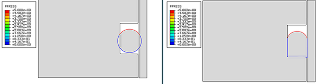
Figure 16: PPRESS showing the region where pressure is applied on the undeformed (left) and deformed (right) shape.
Summary
- Abaqus has options to solve initial overclosures in a strain-free manner and by treating it as an interference fit
- The default is different for general contact (strain-free adjustment) and contact pairs (interference fit)
- In both cases, the other option can be specified as wellThe pressure penetration option is useful when a pressure is prescribed to the part of a contact surface that is not currently in contact.


TECHNIA Simulation provides top tier FEA, Non-linear, and Advanced Simulation Software, Training, and Consultancy. Our dedicated team of more than 65 Simulation experts across 16 countries advise and support your innovation with a wealth of specialist knowledge and experience.
About TECHNIA- Related news and articles straight to your inbox
- Hints, tips & how-tos
- Thought leadership articles

Helping you find the information you’re looking for. Discover webinars, events, FAQ's, case studies and tutorials.
VIEW HUB