

Posted by Dolf Broekaart
Table of contents
Reinforcement of components is often a subject of investigation in several engineering fields. The goal of reinforcing a product could be to increase its strength, reduce costs, reduce weight, increase durability, etc. Different approaches could be followed to try to gain further understanding on the actual contribution of the reinforcement towards optimizing the product. Material properties could be a variable under investigation but also reinforcement orientation is known to be a critical factor affecting the material behavior. In this blog we will focus on the proces to wind a fiber reinforced product and show the ease of understanding the variables involved in the manufacturing process. To show such manufacturing process we will use the commercially available Simulia Abaqus finite element software.
To a great extent the focus of this blog will be on how to create materials that would have properties in different directions. Even though in Abaqus it is relatively straightforward to define orthotropic materials that could simulate a fiber reinforcement with a given orientation, by following such approach we will not be modelling discrete fibers but only their effect in the material properties. Sometimes one might be interested in having more focus on the reinforcements and thus someone could decide to spend more time on modeling the actual fibres. The fibres would have to be physically modelled now, so if the orientation is complex then we would need to spend more time in creating them.
In practice all sort of complex pattern can be observed. Normally an automatic process will roll the impregnated fibres around a product by a combination of axial movements of the fibres carriage and rotations of a mandrel. If one would like include such fibres as reinforcements the drawing process might be possible but will require some complex CAD drawing skills.
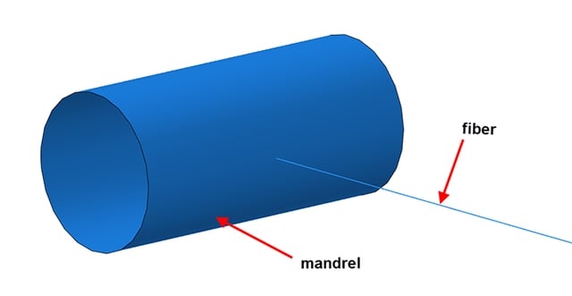
Another option would be to model the actual winding process; i.e. modelling the reeling of the fibres over the product for which the initial geometries would be more trivial, because we would only need a mandrel (tube like) and the fibre, which in this case can be a long flat wire, Figure 1. Once such process is simulated the result will be a fibre network with the desired pattern created during the simulation analysis. Later on, the shape of the created fibre network will be used as reinforcement.
Figure 1: Parts to be considered for the winding process.
Setting up the Model for Filament Winding
Here the pattern of the fibre network will be dictated by the rotating speed and the translational speed of the mandrel.

Figure 2: Boundary conditions applied to model the winding process.
Defining Interactions
Cohesive contact needs to be used to prevent that with changing directions of the mandrel the rolled fibres will sleep and will lose the already achieved pattern.

Figure 3: defining cohesive contact between the fiber and the mandrel.
The definition of the rest of the analysis continues in the standard way of creating an Abaqus model. Truss elements were used for the fibres and a discrete rigid surface for the mandrel.
Results of the Winding Process
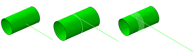
Figure 4: Fibre reeled around the mandrel.
After reaching the limit in one direction the mandrel would move backwards (while still rotating) to create an entangled fibre network. See video, below:
Would you be interested in modelling your reeling process to understand its capabilities?


TECHNIA Simulation provides top tier FEA, Non-linear, and Advanced Simulation Software, Training, and Consultancy. Our dedicated team of more than 65 Simulation experts across 16 countries advise and support your innovation with a wealth of specialist knowledge and experience.
About TECHNIA- Related news and articles straight to your inbox
- Hints, tips & how-tos
- Thought leadership articles

Helping you find the information you’re looking for. Discover webinars, events, FAQ's, case studies and tutorials.
VIEW HUB