

Posted by Christine Obbink-Huizer
Table of contents
Optimization of Hip Implant Done With Simulia Abaqus & Simulia Tosca
In the past, we have already given an example of optimizing a structure using Tosca. Now, I want to revisit this topic and focus specifically on geometry issues. I’ll explain how I obtained the geometry used for optimization, and also show how to get a 3D model of the optimized geometry, that can be used for further finite element analysis.
The Example: A Hip Implant
Though we probably don’t always realize it, we use our hips a lot. After years of loading, they can become damaged and painful. In these cases, replacing the hip with an implant can be a solution. Here we are going to let Tosca design an optimized hip implant, as an example.
The Geometry: Thigh Bone
I’ll start from a model of the thigh bone or femur, taken from grabCAD (Figure 1). This is a SolidWorks part, and with Abaqus 2020 it can be directly imported.
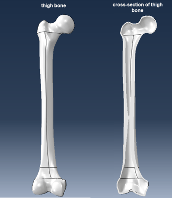
Figure 1: The geometry of the thigh bone, showing the full part and a cross-sectional view.
Based on this, the space that can be used for the hip implant will be determined. The thigh bone is hollow and modeled as a solid. First, two regions are partitioned that will be used for load application (Figure 2). It is assumed that a muscle is adhered to one region, and the hip is in contact in another region.
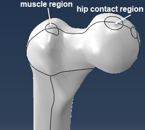
Figure 2: Upper part of thigh bone showing partitioned regions that will be used to simulate loads due to the muscle and due to hip contact.
Next, datum planes are made, to partition the thigh bone so that the region that is to be optimized is separated from the rest (Figure 3). This is done in such a way that the regions were loads are applied are not optimized. Because in reality these regions interact with other parts, we do not want to interfere with them.
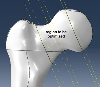
Figure 3: Upper part of thigh bone showing partitions used to separate the region that will be optimized from the rest.
A copy is made, so that this can be used as starting point for both the part that will remain the same and the part that will be optimized.
Part That Will Remain the Same: Bone and Head
The part that will remain the same is obtained by removing the faces in the region to be optimized. This automatically also removes the cells and leaves us with the geometry of interest. Bone material properties are assigned to the main part of the thigh bone, while titanium properties are assigned to the head, which is part of the implant (Figure 4). The part is meshed.
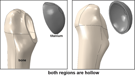
Figure 4: Upper region of the part that will not be optimized, also indicating which material properties are assigned where.
The Part That Is to Be Optimized
In order to do the optimization, we need a part corresponding to the geometrical region where material is allowed. In this case, the outer surface of the original geometry that was deleted previously is used, as well as the space inside the top of the bone and the titanium head. To get a solid geometry of space inside the bone and titanium head, the outer bone and titanium head surfaces are removed, to obtain a shell model of the internal surfaces. The bottom region is removed, the open edge is covered and a solid is created based on the outer shell (Figure 5).
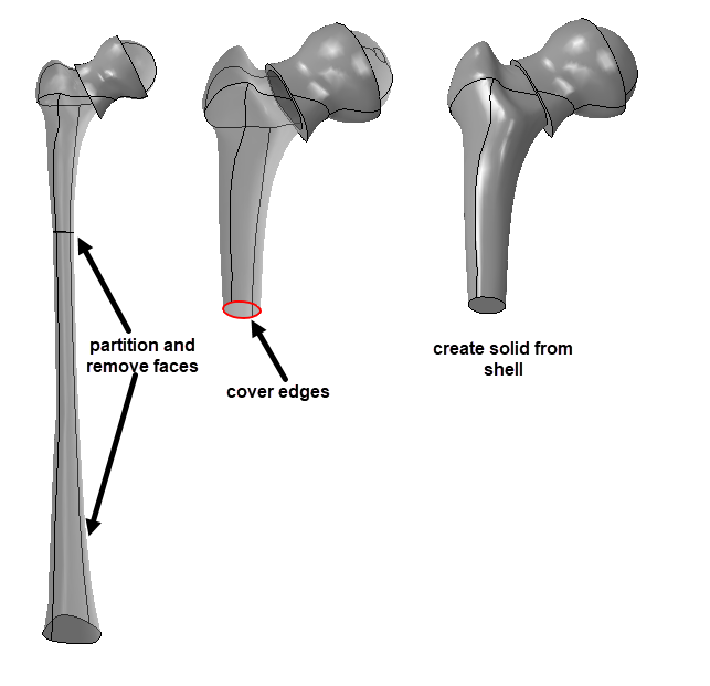
Figure 5: Strategy to obtain the part that is to be optimized: based on the inner faces of the bone a closed outer surface is obtained, from which a solid is created.
This leads to a part that precisely fits into the part that is to remain the same. Titanium material properties are assigned, and the part is meshed.
Model Set-up
Kinematic couplings are made to couple the knee region, hip contact region and muscle region to individual reference points. The knee reference point is fully constrained, while loads in all three directions are applied to the hip and muscle reference points (Figure 6).
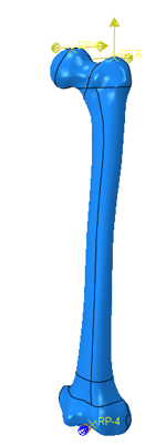
Figure 6: Thigh bone and implant model showing the loads and boundary conditions applied.
These loads were based on literature (Figure 7).
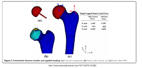
Figure 7: Image on which loads are based, taken from Tai et al. BMC Musculoskeletal Disorders 2014, 15:262.
The outer surface of the part that is to be optimized is tied to the internal surface of the part that is to remain the same and contact is defined on the faces that we obtained by partitioning using datum planes as shown in Figure 3. A static, general step is used.
Optimization
A condition-based optimization is performed, with the objective of minimizing the strain energy density of the optimized part, while its volume is constrained to be 0.4 times the initial volume. With this, we should get the stiffest structure for the given amount of material, using a computationally efficient algorithm.
Results
A video of the optimization can be found here:
The resulting part looks like this:
The lowest part of the implant, inside the bone is solid. There are connections with the load application points (Figure 8). Because the hip load is not applied at the center of the semi-sphere but close to the edge, the connection from the central region to the semi-sphere also goes to this point. The central region is hollow and there are holes in the outer structure.
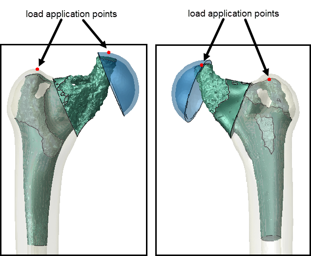
Figure 8: The optimized implant geometry, along with the connecting parts.
Geometry Extraction
The result of the optimization is visualized by making a view cut based on the relative element density. The mesh hasn’t changed, we are simply deciding whether or not to view elements based on the results of the optimization. If we want to use this design later on, we have to describe the geometry. Abaqus offers several extract options for this (Figure 9).
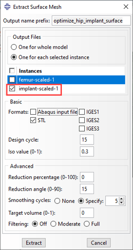
Figure 9: Extracting the surface of the optimized shape.
Here we extract an .stl file for only the optimized part. An Iso value cut-off value is selected, defining at what relative element density an element is considered full. Smoothing will be applied, so the roughness caused by defining a shape based on elements will be less.
Solid Geometry From STL
The .stl file only defines the outer surface, while a solid is needed if we want to use the geometry in a further analysis. Obtaining a filled .stl file can easily be done using SolidWorks: select ‘open’ and ‘mesh files’ as type (Figure 10).
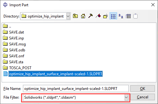
Figure 10: Opening and .stl file in SolidWorks.
Click on ‘options’ (indicated in Figure 10), and select ‘import as Solid Body’ in the system options (Figure 11).
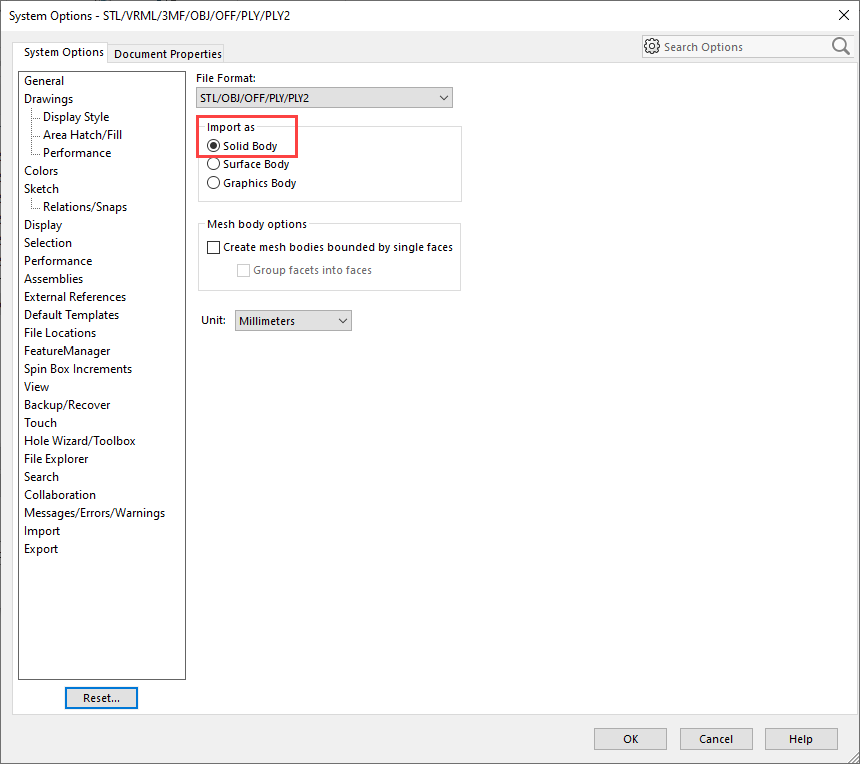
Figure 11: Open .stl files as solid bodies.
If the result is saved as a SolidWorks part (.sldprt) it can directly be imported in Abaqus 2020. (For older versions, a file type such as .sat or .stp must be used).
Comparison of Extracted Geometry to Optimization Result
To see whether the extracted geometry agrees with the optimized model, a copy of the original model is made, in which the to be optimized part is replaced by the part that is based on the extracted geometry. The outer surface consists of many triangular faces. In this case, it is meshed as is, but it is also possible to use virtual topology in order to have more control over element shapes and sizes. In Figure 12, the stress results that were obtained during the optimization (left) are compared to the stress results of the extracted geometry (right).
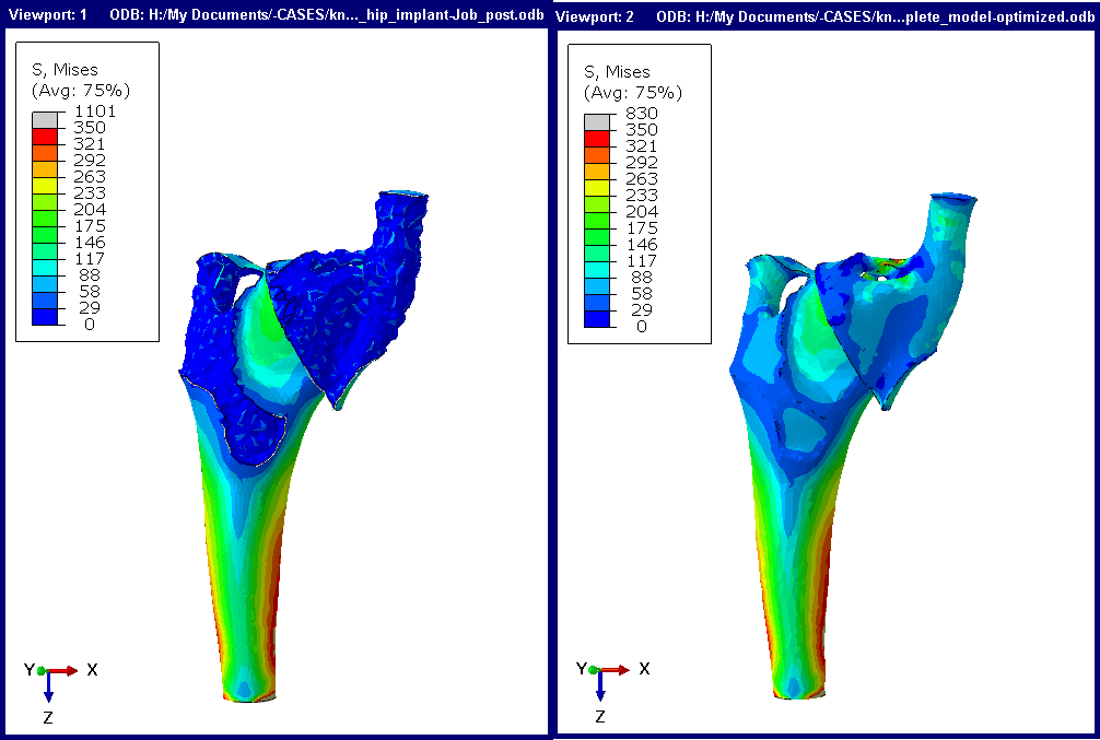
Figure 12: von Mises stress in implant during optimization (left) and using extracted geometry (right).
The geometry and stress in both models are not exactly the same. Especially in regions where there are small features (close to the element size), differences between the two geometries may occur. Stresses on the outer surface that is obtained by optimization are not available directly, because the surface is not available directly. This explains why stresses on the original outer surface of the part match more closely than on the part of the outer surface that is obtained by optimization.
Conclusion
- Though Abaqus isn't a CAD program, it offers almost all of the geometrical tools that were needed for this example.
- Filling up an .stil file is the only thing that was done with a different progam (SolidWorks). Abaqus can import stl's, but it treats each face as an element. In principle, these can be converted to geometrical faces and a solid can be build based om them, but this is much more time consuming than using SolidWorks.
- It is necessary to extract a surface from a Tosca optimization in order to do further analysis.
- Rerunning the analysis with the extracted geometry can provide additional insight, especially into what is happening on the part of the outer surface that is obtained by optimization.
Next Step
The next step will be, to simulate the additive manufacturing of this part. This will be discussed in a later blog to follow next week. Read it right here.


TECHNIA Simulation provides top tier FEA, Non-linear, and Advanced Simulation Software, Training, and Consultancy. Our dedicated team of more than 65 Simulation experts across 16 countries advise and support your innovation with a wealth of specialist knowledge and experience.
About TECHNIA- Related news and articles straight to your inbox
- Hints, tips & how-tos
- Thought leadership articles

Helping you find the information you’re looking for. Discover webinars, events, FAQ's, case studies and tutorials.
VIEW HUB