
Posted by Paul Bolcos
Categories
composite analysisTable of contents
To say that the Dutch love biking is a bit of an understatement, considering there are ~23 million bikes for ~17 million people. What is more surprising though is that some Dutch own mountain bikes, despite not having any mountains or (significant) hills for that matter.
The bike frame is usually made out of aluminum, titanium, steel or carbon fiber. The choice of material is mainly related to the weight of the frame, but what about the loading? In this blog, I will simulate each frame, including the composite one, in Abaqus/Explicit.
Introduction
The main components of a frame are shown in the figure below. The design is usually assessed using ISO 4210-6 using physical testing or even FEA.
Figure 1. Components of a bike frame.
In terms of materials, the frame can be made from either: aluminum, titanium, steel or carbon fiber. Carbon fiber bikes are preferred by professionals due to lower weight (lower density). However, this comes at a cost.
In most riding conditions, the differences should be minimal for the average user, with maybe a more comfortable ride in the aluminum and carbon frames. But what happens during a crash? The following scenario is not uncommon for mountain bikers (see Figure 2). You find yourself in front of an obstacle (i.e a log), you try to jump over it and for some reason or another you come up short. Now, you got yourself a nice dent in the down tube.
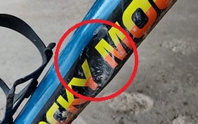
Figure 2. A dent in a tube.
Whether you believe the bike is "safe" to ride or not depends more on you, but is there a difference between the materials?
The FE Model
The frame geometry was obtained from GrabCad (link here). After some defeaturing, the 3D solid was converted to shell elements and meshed using S4R and S3 elements. As this is more of an example, the log was modeled as a rigid body.
Four material properties were used: Aluminum (AL6061), Titanium (TI6AL4V), Steel (ANSI-4340) and Carbon fiber (UD carbon/epoxy T300/M18). The material properties were taken from MatWeb and are shown in the Table 1. T300/M18 was defined as Elastic lamina.
| Material | E (MPa) | ν (-) | ρ (tonne/mm3) | ||||
| AL6061 | 69000 | 0.33 | 2.70e-9 | ||||
| TI6AL4V | 113800 | 0.31 | 4.43e-9 | ||||
| ANSI-4340 | 205000 | 0.32 | 7.85e-9 | ||||
| E1 (MPa) | E2 (MPa) | ν12 (-) | G12 (MPa) | G13 (MPa) | G23 (MPa) | ρ | |
| T300/M18 | 170000 | 9000 | 0.34 | 4800 | 4800 | 4500 | 1.80e-9 |
In addition, for the non-composites, the yield stress, plastic strain and fracture strains were obtained from MatWeb. For the composite we used Hashin Damage, with properties from Table 2.
| Longitudinal tensile strength | Longitudinal compressive strength | Transverse tensile strength | Transverse compressive strength | Longitudinal shear strain | Transverse shear strain |
| 2050 | 1200 | 62 | 190 | 81 | 81 |
For the carbon frame five plies were defined, with a ply thickness of 0.2 and rotation angles (see Figure 3). The values used here are representative, since the actual layup and ply orientation in carbon frame bikes is not easily accessible. Similar procedures for modelling composites can be found in some of our previous blogs, for instance bolted composite joint and loading of a composite flanged tube. For the non-composites, the shell thickness was matched to the carbon frame.
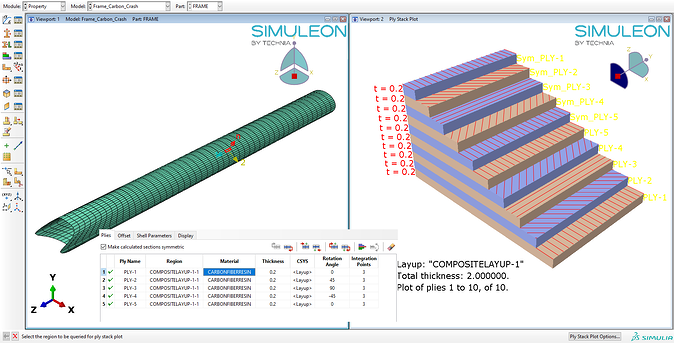
Figure 3. Overview of composite layup for the frame.
Loading
The full assembly is shown in the figure below. As we are trying to simulate essentially a crash, Abaqus/Explicit was used and a simulation time of 0.1ms. In terms of loading, the frame had a predefined velocity of 4800 mm/s (~17.3 km/h), while the log was fixed for all degrees of freedom.
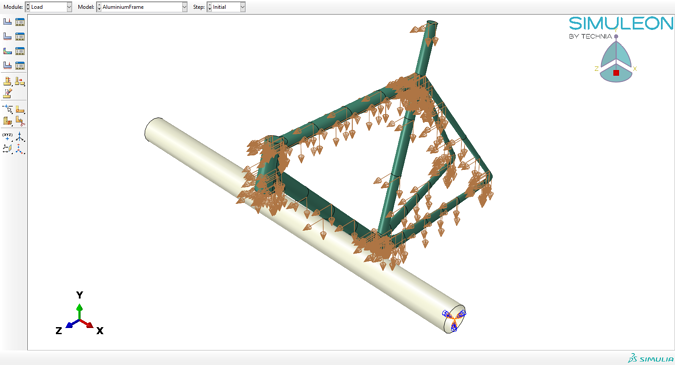
Figure 4. Overview of the frame assembly, loading and boundary conditions.
Results
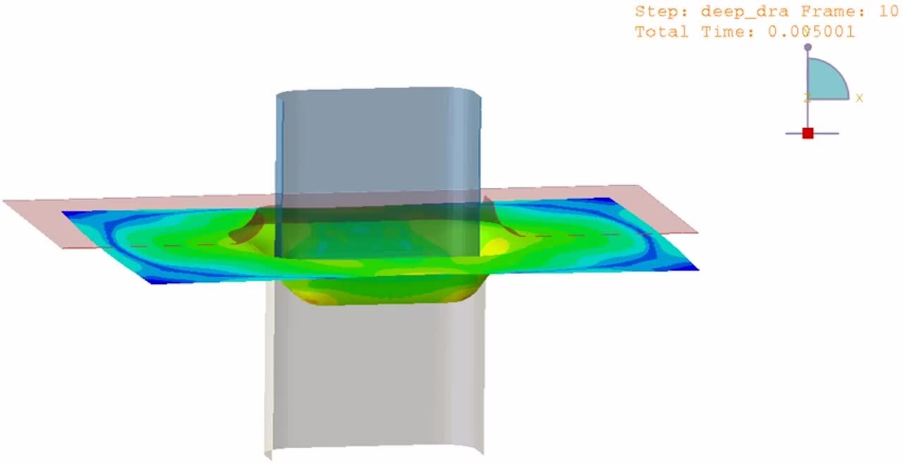
The animation below shows the stress concentrations on the bottom of the frame (the down tube). For all, the upper limit is set to 400 MPa. Expectedly, both the titanium and steel frame show region above yield (Figure 5 and 6), and it's likely that both will show a dent in the frame, similar to Figure 2.
Figure 5.Down tube stress concentrations on the steel frame.
Figure 6.Down tube stress concentrations on the titanium frame.
Moreover, both the titanium and steel frames show stress concentration near the main connections between the head and top tube and between the seat and down tube (Steel frame shown in Figure 7, Titanium frame not shown - similar distribution as in Figure 7). This would indicate that those regions are also at risk and higher impact speeds may cause the frame to buckle also in those regions.
Figure 7. Stress concentrations on the steel frame at other join regions.
The carbon frame also shows damage in the same regions (Figure 9), but arguably less then the titanium and steel frames, while the aluminum frame shows no stresses above yield (Figure 8). Neither the aluminum nor the carbon frame showed high stresses near the other two join regions. This would mean that aluminum and carbon frames should still be a better choice as frame material than titanium for instance, even though both options are not cheap.
Figure 8. Down tube stress concentrations on the aluminum frame.

Figure 9. Down tube stress concentrations on the carbon fiber frame.
Conclusion
In this example, I have shown how to simulate a bike frame crash using Abaqus/Explicit. Aside from more traditional materials, I've shown at least the basic process of creating a composite material. Further design improvements can be made in all designs. For instance both topology and sizing (i.e. shell thicknesses) optimizations could be run on these frames to find an optimum design. For the composite frame, knowing the actual layup would made such simulations more accurate. Then different layup thicknesses and orientations could be simulated.
If you're new to Abaqus be sure to check out some of our training sessions.

TECHNIA Simulation provides top tier FEA, Non-linear, and Advanced Simulation Software, Training, and Consultancy. Our dedicated team of more than 65 Simulation experts across 16 countries advise and support your innovation with a wealth of specialist knowledge and experience.
About TECHNIA- Related news and articles straight to your inbox
- Hints, tips & how-tos
- Thought leadership articles

Helping you find the information you’re looking for. Discover webinars, events, FAQ's, case studies and tutorials.
VIEW HUB