

Posted by Christine Obbink-Huizer
Table of contents
When producing a part, you want it to match the design, the geometry. How to achieve this is not always evident.
For example, when the part is created from sheet metal by pressing it between an upper and lower die, the final part may not fully match the space in between the dies due to the spring back effect. If the deformation would be fully plastic, then the deformed shape will not change during unloading. If it is partially elastic, then the elastic deformation is recovered upon unloading and hence the final shape differs from the shape between the dies. In this blog I’ll give an example of this effect, showing that we can model it with Abaqus.
Method: Geometry
The example I’ll use here, is the forming of a simple bracket. The geometry of the forming dies is shown below.
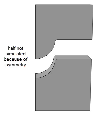
Only a quarter of the geometry is simulated, for reasons of symmetry.
The shape of the blank (the sheet metal) is shown below.
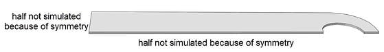
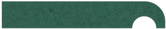
Because the thickness of the blank (0.4 mm) is small compared to its other dimensions (around 20x120 mm), it is modelled with shell elements. The mesh is shown below.
Method: Material
For the dies, no material properties are needed, because they are considered rigid. This simplifies the analysis but does not allow us to see stresses and strains on the dies. It is possible to make them deformable if the stresses and strains on the dies are of interest.
For the blank, we will use a stainless steel (ANSI 316). When the material is formed, it is deforming plastically. It is therefore important to include plastic material properties. In this case the initial yield strength is 172 MPa, and plastic data is described up to a plastic strain of 0.0045 and a stress of 220 MPa.
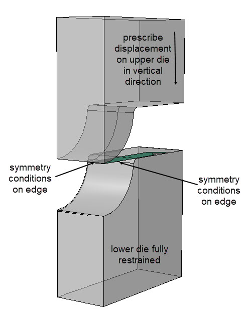
Method: Set-up
The blank is positioned on the lower die taking into account its shell thickness. The upper die is positioned so that it just touches the blank, still taking into account the shell thickness. Two steps are included. During the first step, the upper die is moved downwards, up to the point that the space in between the dies matches the thickness of the blank. During the second step it is opened again, so spring back can be observed. Smooth steps are used, to gradually apply the displacement and limit dynamic effects. The lower die is fully constrained during both steps. Symmetry conditions are prescribed to the blank.
Contact is included with a friction coefficient of 0.15.
Abaqus/Explicit is used for the loading step. The results from this analysis are loaded into Abaqus/Standard to perform the unloading (spring back) step.
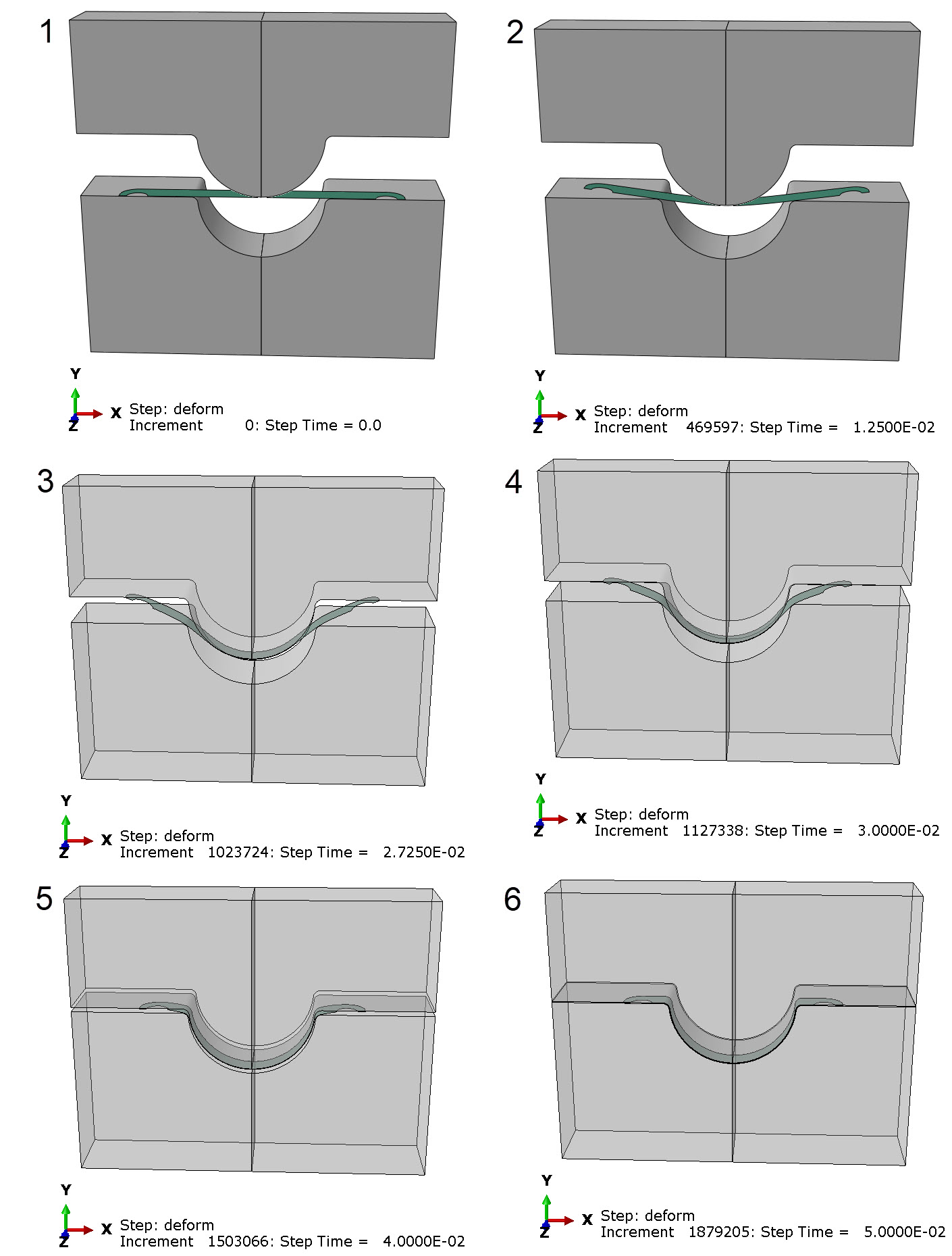
Results: Metal Forming
As expected, the upper die contacts the blank in the middle and starts bending it. The outer regions go up as the center goes down. When the outer regions touch the die as well the restrain it until the blank touches the dies all along its outer surfaces and is forced into shape. This process is shown in the series of images below.
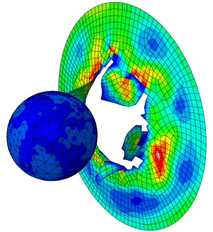
Results: Spring Back
When the dies are removed, any elastic deformation is recovered. The resulting shape is shown below.
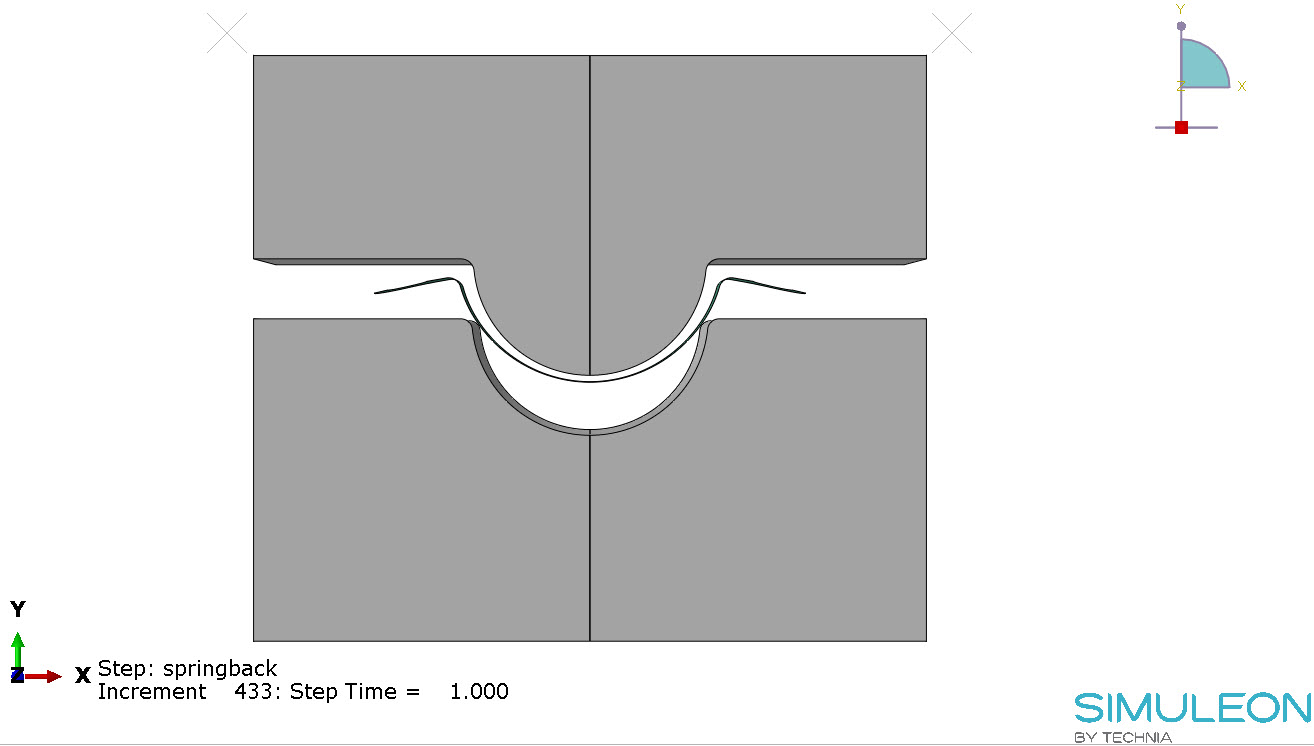
The final shape is clearly different from the shape between the dies, due to spring back.
Conclusion and Advantages of Simulation
This example shows that Abaqus is capable of simulating both the forming process and the unloading afterwards. This allows us to determine the amount of spring back occurring.
Though the example shown is simple, the same techniques and principles can be applied to more complex situations, for example in car manufacturing. Based on the output of such an analysis, changes to the die design can be made.
Thus, the design of the dies can be improved and costs reduced, by simulating the shape after spring back before the – often costly – dies are produced.
Do You Want to Discuss Your Challenges With Us?

TECHNIA Simulation provides top tier FEA, Non-linear, and Advanced Simulation Software, Training, and Consultancy. Our dedicated team of more than 65 Simulation experts across 16 countries advise and support your innovation with a wealth of specialist knowledge and experience.
About TECHNIA- Related news and articles straight to your inbox
- Hints, tips & how-tos
- Thought leadership articles

Helping you find the information you’re looking for. Discover webinars, events, FAQ's, case studies and tutorials.
VIEW HUB