

Posted by Christine Obbink-Huizer
Table of contents
Simulating Welding Using the Abaqus Welding Interface - Part 2
In a previous blog, I have shown how to model welding for a simple case with Abaqus. Here sequential thermal-structural analysis is used to apply temperatures calculated in a thermal analysis in a subsequent structural analysis. Also, the model change option is used to remove and reactivate bead material, simulating its deposit.
A similar approach can be used for more complex cases. However, defining such a model can be very time consuming because many steps with different model changes, film conditions etc. need to be defined.
To simplify the process of setting up such a model, the Abaqus Welding Interface (AWI) has been developed.
The Abaqus Welding Interface is freely available. More information on how to obtain and install it can be found here: https://www.3ds.com/products-services/simulia/products/abaqus/add-ons/extensions/. A download link to the newest version is available here: 3ds.one/jcP50L (3DS Passport Required).
Initial Model Creation
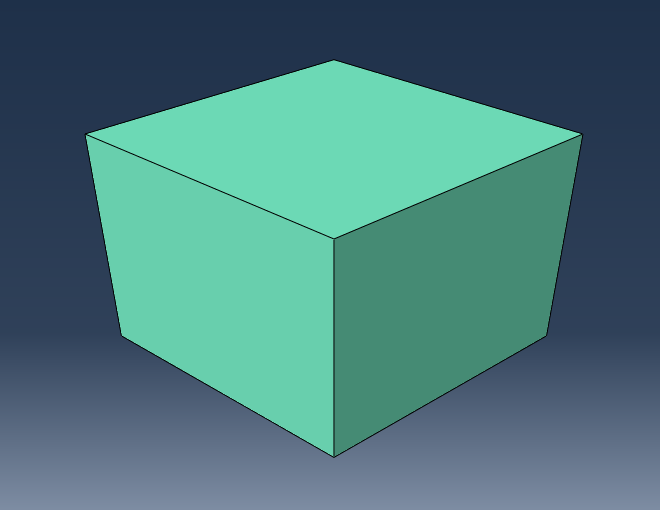
In the model database, a model is created containing the base and weld geometry in a single part, partitioned in different regions and meshed. The geometry shown in Figure 1 is used.

Figure 1: The geometry.
Material properties (both thermal and structural) and sections are defined and assigned and an instance of the part is created in the assembly.
Opening Interface
When the files are stored in the correct place, the Abaqus Welding Interface can be opened by clicking Plug-ins --> Abaqus Welding Interface.
An extra tab then opens, named Abaqus Welding Interface (Figure 2).
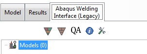
Figure 2: The Abaqus Welding Interface tab.
Creating Welding Model
By right-clicking on Models in the tree on the Abaqus Welding Inteface tab, a new weld model can be created. The Weld Model dialog box then opens (Figure 3). In this dialog box, the heat-transfer model and part are selected from drop-down lists. The unit system has to be selected as well. SI units and British Units are default options, other unit systems need to be defined manually. By clicking on the ‘set defaults’ button, various parameters such as the initial temperature and Stefan-Boltzmann constant are set automatically. Finally, the location of the base material and the base material name are selected. The model is now included in the tree, with subcategories of Welds, Pass Controls, Passes, Job Controls and Jobs. These will now be defined. They have to be defined in this order; e.g. it is only possible to create Pass Controls once the Weld definition is complete.
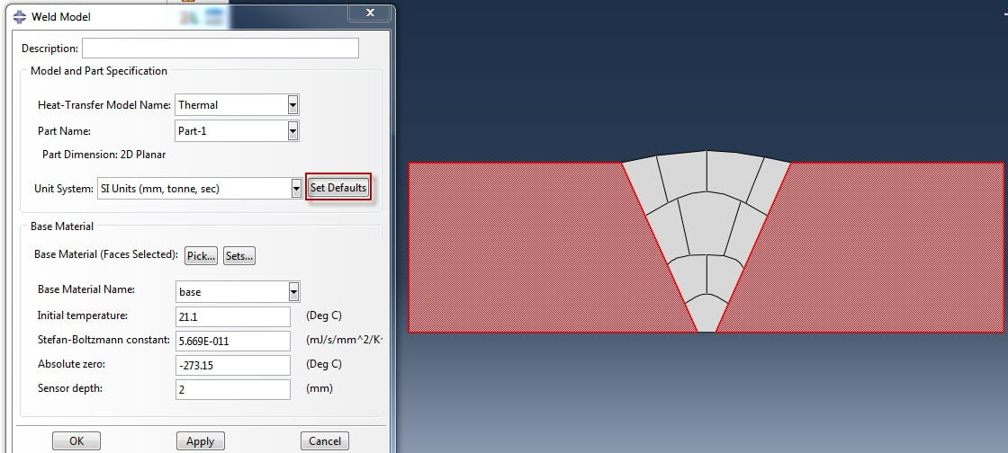
Figure 3: The Weld Model dialog box, also showing the region indicated as base material.
Defining Welds
First, the weld properties are defined: a Weld Name and the previously defined weld material are specified. The initial melt temperature of the weld, the target torch heat up temperature, etc. need to be defined as well. It is possible to use default values for this, by selecting: Set Defaults (Figure 4)
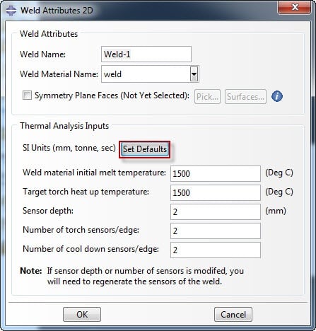
Figure 4: Specifying Weld Attributes.
The faces of the beads are then selected. This can easily be done by selecting the faces for the first bead, and then clicking the middle mouse button to confirm. The faces for the second bead can then be selected and confirmed until all beads are defined. The beads are defined in the order they will be laid down later on (Figure 5). While this is not necessary, it simplifies defining the passes. A weld with 10 beads is now visible in the tree.
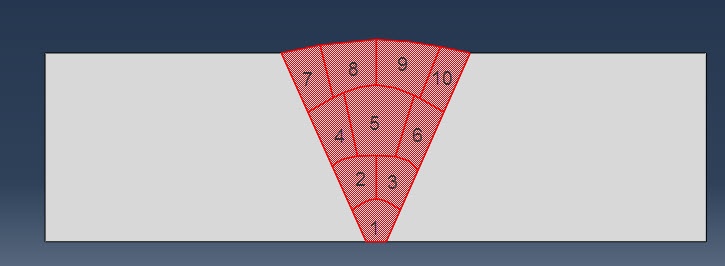
Figure 5: Order of bead selection.
Defining Pass Controls
The next step is to define pass step controls. Later on, different steps are created automatically and here their properties are defined. These steps included a heating up step, a cool down step and steps to remove and include bead material. (The step definition corresponds to what was explained in the previous blog).
There are properties for the torch step, when the material is heated up as the torch passes. These include the time period, initial time increment etc. Default values are available for most properties. If a Fortran compiler is installed and linked to Abaqus, sensors can be used: once the sensors reach the specified temperature, the step is terminated. For the temperature application there are two options: ‘ramp’ and ‘ramp and hold’. In the first case the complete time period is used to ramp up the temperature, in the second case the temperature is first ramped up and then held constant.
For the cool down step, when the model cools down after bead deposition, similar properties need to be defined. Again you can choose to terminate the step based on sensors.
Optionally, a reset temps step can be included, to bring the whole model back to a specified constant temperature (e.g. room temperature) before the next weld begins.
Furthermore, film and radiation properties can be set. By default, film and radiation conditions will be defined for the beads and for the base. These regions change during the analysis, to reflect the current external faces of the beads and non-covered part of the base. Additional film and radiation properties can be added (Figure 6).
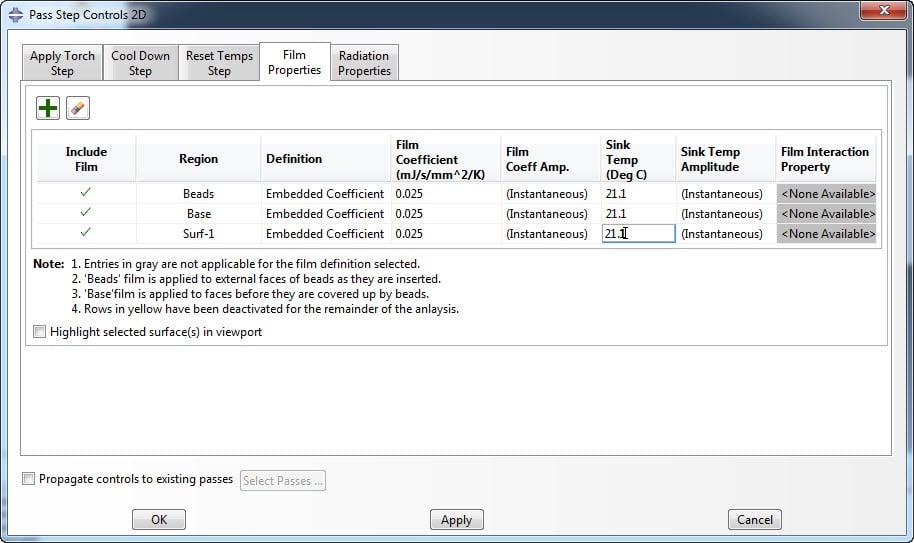
Figure 6: Setting the film properties as part of the part step controls.
Passes
Next, the passes are defined. There are different ways to do this: automatic, by weld and by bead. The automatic option will define the passes in the same order the beads were defined, so selecting this option and clicking on the double arrow will create a pass for each bead in the intended order.
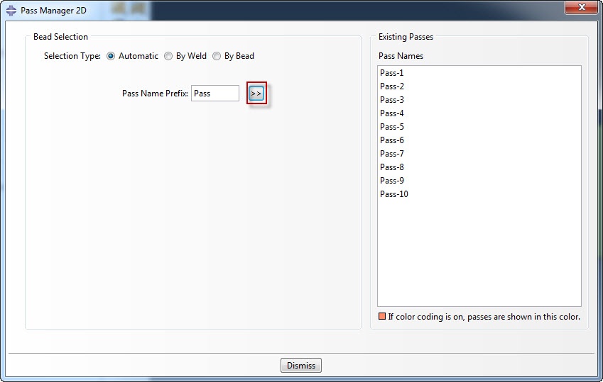
Figure 7: Pass definition.
Job controls
When the passes are defined, the next step is to define the job controls. A name for the heat transfer job and for the stress analysis job are given, and the amount of output to be stored is selected.
There are two options for bead removal in the stress analysis: pass level and model level. For pass level, the beads are active in the model and deform with it up until their corresponding torch step. When the bead is deposited it is first removed in a short model-change step and then put back in place strain free and with the temperature from the thermal analysis. (This is what was done in the previous blog). With model-level bead removal, all the beads are removed at the beginning of the analysis and reinserted during the corresponding torch step.
With pass level bead removal, the beads may influence results while they are not there yet in reality. On the other hand, with model-level bead removal, the surrounding material can be deformed so that the elements don’t nicely fit anymore and become distorted.
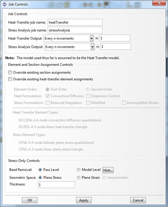
Figure 8: Defining the job.
Jobs
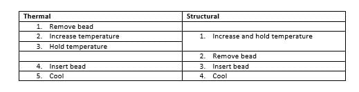
Finally, the jobs can be defined. This will remove all previously defined steps and step dependent entities in the heat transfer model and completely delete and rebuild the stress model. Afterwards, there are two models in the model database: a structural as well as the thermal model. In the thermal model, the steps are automatically created: for each pass a temperature increase, temperature hold, bead insertion and cool down step. Furthermore, the requested film conditions, that differ for different passes, the model changes to remove and insert the beads, and the boundary conditions to prescribe temperatures are created. In the structural model, steps are created, in this case a temperature increase, bead removal, bead insertion and cool down step for each pass. Model changes and prescribed temperature fields are also included. In total, there are 42 steps in the thermal model, 30 interactions and 10 boundary conditions. In the structural model there are 41 steps, 10 interactions and 22 predefined fields. Defining all this manually would be extremely time consuming. Additional boundary conditions etc. can be defined after the automatic jobs have been created.
Results
The temperature field and von Mises stress during the analysis can be seen in the video’s.
In the thermal analysis, the beads are initially not in place and only added when they are deposited. In the stress analysis they are removed just before being deposited, so they are present at the start of the analysis. If the beads would be removed at model level, they would not be visible at the start of the analysis.


TECHNIA Simulation provides top tier FEA, Non-linear, and Advanced Simulation Software, Training, and Consultancy. Our dedicated team of more than 65 Simulation experts across 16 countries advise and support your innovation with a wealth of specialist knowledge and experience.
About TECHNIA- Related news and articles straight to your inbox
- Hints, tips & how-tos
- Thought leadership articles

Helping you find the information you’re looking for. Discover webinars, events, FAQ's, case studies and tutorials.
VIEW HUB