
Posted by Nikolaos Mavrodontis
Table of contents
In this blog post we will be discussing about the symmetric model generation feature that is incorporated in Abaqus. This feature is targeted towards reducing the solution time needed for an analysis. We will first present the supported features and limitations, followed by an exemplary analysis of a flanged connection wherein this feature can be used.
Supported Geometry Features
A 3d model can be created by:
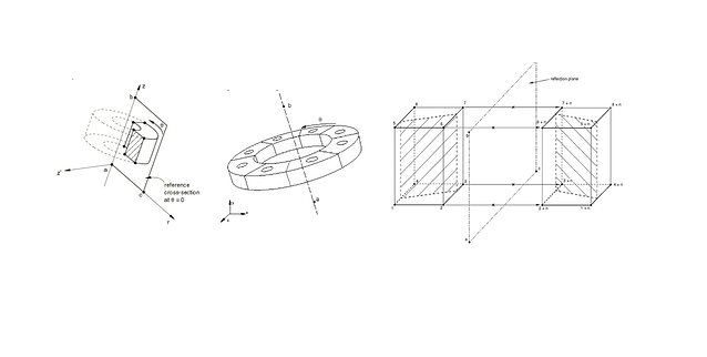
- Revolving an axisymmetric model about its axis of revolution
- Revolving a single 3d sector about its axis of symmetry (will be showcased here)
- Combining two parts of a symmetric three-dimensional model, where one of the parts is the original model and the other part is obtained by reflecting the original model through either a symmetry line or a symmetry plane.
- For features 1-3, both 3d geometry generation as well as 3d geometry generation plus results transfer are supported.
A graphic detail of the supported features is shown in figure 1 below.
-2.png?width=640&name=Picture%201%20(features)-2.png)
Figure 1: Supported geometry features (courtesy of Simulia).
Prerequisites
- Original model input file must be flat (Do not use parts and assemblies in input files option must be checked from the Model Edit Attributes menu).
- Restart files must be generated for the original model
Tip: Make sure you create sets and surfaces with meaningful names based on your modelling needs. You should also create full sets of the instances included in the original model. This will allow you to have display groups readily available for post processing. Remember that since the input file will be flat, you will not be able to select individual part instances from the viewport, rather than element or node sets.
Limitations
- First and second order elements cannot be used together in the axisymmetric model.
- Non axisymmetric elements such as springs, dashpots, beams and trusses will be ignored in the model generation.
- Only surface based contact pairs can be revolved. Models using general contact cannot be revolved. Contact conditions modelled with contact elements will be ignored in the model generation.
- Most types of kinematic constraints cannot be revolved. However surface based constraints and embedded element constraints defined in the original model will be generated automatically in the new three-dimensional model.
- Only stress/displacement, heat transfer, coupled temperature-displacement, and acoustic elements can be revolved.
- Implementation of the symmetric model generation feature via the CAE is not supported
Element correspondence
The element type used in the original model, determines the element type in the new three-dimensional generated model. You can specify whether the new element should be either a general three-dimensional element or a cylindrical element. General and cylindrical elements can be used in the same model. There is also the option to discretize the generated model by applying biasing or by even customizing the number of elements per angular sector (for a revolved 3d generated model). The correspondence between axisymmetric and three dimensional element types can be found in the respectful section in the Abaqus documentation.
Flange Example
For our example, we will be using a 3d sector model (supported geometry feature no 2) representing a flange segment, comprising of two flange parts and an M48 bolt connecting them. First off, the pretensioning of the bolt will be performed. This type of loading is symmetric for the flange with respect its the symmetry axis. Next , this 3d sector model will be revolved around the symmetry axis in order to produce the generated model together with the solution fields (corresponding to the stresses-strains relating to pretensioning). The original model comprises of a 20 degree sector. The generated full flange 3d model will therefore comprise of 18 sectors and 18 bolts in total. As a subsequent analysis step, a moment around the Z-axis (unsymmetric loading) will be applied on the generated model.
Implementation - Original Model
A detail of the discretized original 3d sector model is shown in figure 2.
-1.png?width=300&name=picture%20%202(discretized%20original%20model)-1.png)
Figure 2: The discretized original 3d sector model.
A detail of the pretension stress results (view cut) are given in Figure 3.
.png?width=640&name=picture3(results_detail_original).png)
Figure 3: Pretensioning step stress and contact pressure results.
Generated Model (full 3d)
As a first check, in order to check that the discretization of the generated model is adequate, and that the symmetric model generation feature works as expecte overall, we can run the following command via the cmd window. What is demonstrated next, focuses on purely geometry generation and not results transfer (yet).
We run the following command via the cmd--> “abaqus datacheck job=generated_model_full_3d.inp “
,where “generated_model_full_3d” corresponds to the input file of the generated model, followed by the input of the original model's name as shown in Figure 4.
-1.png?width=640&name=picture%204(datacheck%20input%20file)-1.png)
Figure 4: Datacheck command window detail.
A detail and description of that input file is given in Figure 5.
-4.png?width=640&name=picture%206%20(full_3d_datacheck_input_file)-4.png)
Figure 5: Generated model input file detail for datacheck.
What is shown next in Figure 6, is the generated geometry upon running this input file via the cmd.
-4.png?width=640&name=picture%205%20(discretized%20full%203d%20datacheck)-4.png)
Figure 6: Generated geometry upon running the datacheck command on the generated model input file.
Results transfer and subsequent analysis
Up next , we will also transfer the results that were produced in the original sector model, and generate the solution field at the end of the sector model pretensioning analysis for the entire 3d geometry model. At the same input file, the subsequent step (that can correspond to an asymmetric load for example), together with its respectful loads, boundary conditions and output requests are included. The subsequent step will now exlusively concern the full 3d geometry. The detail of the generated model’s input file is given below, in Figure 7:
.png?width=640&name=picture%207%20(full_3d_results_transfer_input_file).png)
Figure 7: Generated model input file detail for results transfer and subsequent analysis.
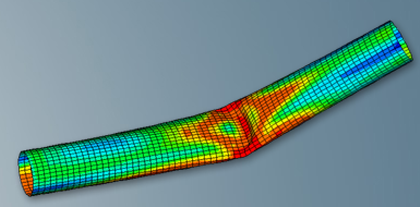
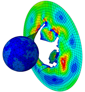
A detail of the results of the full 3d model in terms of the change in contact pressure on the flange due to a bending moment acting on the full 3d geometry , is given below, in Figure 8.
-1.png?width=640&name=picture%208%20(results1_generated)-1.png)
A video of the deforrmation experience by the complete flange due to the bending action is given below.


TECHNIA Simulation provides top tier FEA, Non-linear, and Advanced Simulation Software, Training, and Consultancy. Our dedicated team of more than 65 Simulation experts across 16 countries advise and support your innovation with a wealth of specialist knowledge and experience.
About TECHNIA- Related news and articles straight to your inbox
- Hints, tips & how-tos
- Thought leadership articles

Helping you find the information you’re looking for. Discover webinars, events, FAQ's, case studies and tutorials.
VIEW HUB