
Posted by Dolf Broekaart
Categories
Topology OptimizationTable of contents
In the current blog we will show some capabilities of one of Simulia’s extended products, Tosca. As a quick recap, based on your license you can use your tokens to run Simulia Abaqus or you can also use your licenses to run products of the extended portfolio:
- Abaqus (Finite Element Analysis)
- Fe-Safe (Fatigue Analysis)
- ISight (Parametric Optimization)
- Tosca (Non Parametric Optimization)
Non Parametric Optimization
We will focus on Tosca which is a tool for non-parametric optimization. Contrary to I-Sight which is a parameter based optimization tool in Tosca a general design space can be created and based on the requirements the software will determine a natural shape that can carry the necessary loads at a minimum weight-expense. In Tosca as long as some criteria is satisfied then the shape will be freely defined inside the domain defined as designed space. On the other hand in I-Sight the parameter(s) must be identified, therefore it should be something that already exists, such as a diameter, a radius, a thickness, a Young’s Modulus, etc.
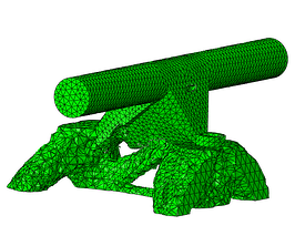
In the current blog we will show a non-parametric optimization performed on Simulia Tosca. The product that we will optimize is a skateboard truck, see Figure 1. The skateboard truck was drawn natively in Abaqus and is therefore a simplified representation, Figure 2. However, it can fully show the goal of starting with a gross design and let the software help you to have a new design that hardly would have been the first iteration in the design process. For the simulation the truck is fixed in the areas where the screws are placed and is loaded vertically in the areas of the wheels representing the reaction of the ground when a person stands on the board.


Figure 1: Skateboard, left and un-mounted skateboard truck with wheels, right.
When doing optimization the goal is to define the possible stiffest part at the lowest amount of material (with a fraction of the initial volume). Thus, removing material while still having a part that can withstand the design loads is much what this process is about. Therefore, you can think that you need to have a generous volume where material will be removed and you will end up with a product that can be close to the final design. That is the reason why the parts drew in the truck, Figure 2, are big and thick in comparison with that from Figure 1 right.


Figure 2: Initial design of the skateboard truck.
Define the Design Space
Step by step in an optimization process you need to create an optimization task and define the design space, Figure 3. In this case we defined everything as the design space, thus, in principle, material can be removed from every region in the model.

Figure 3: Creating an optimization task and selecting the whole model as design space.
Define Design Responses
Then, a design response needs to be created. We have created a design response for Energy stiffness measure and another design response was created for the volume, Figure 4.
Figure 4: Creating a design response for Energy stiffness measure and for volume.
Create Objective Functions
The design response for energy stiffness measure will be minimized by creating an Objective function, this will produce the stiffest possible solution, Figure 5.

Figure 5: Objective function to minimize the energy stiffness measure.
Create Optimization Constraints
With the other design response (volume) we will create a constraint so that the response is limited to a certain percent of the initial volume, Figure 6. The volume is related to the mass of the system which we are trying to minimize.
Figure 6: Constraining the final response to a fraction of the initial volume.
Creating Geometric Restrictions
Initially we have defined the whole model as part of the design space but some areas cannot be redesigned, for instance the holes for the bolts/screws and the external sides of the axle where the wheels should be mounted, highlighted in red in Figure 7. This restrictions can be considered and under Geometric restrictions. Other type of geometric restrictions not considered here could be, demold control, planar control, rotational symmetry, cyclic symmetry, point symmetry and member size. The latter was also prescribed to control the size of the members, sometimes the software can create thin or thick members that later on represent problem during the manufacturing process.

Figure 7: Frozen areas where material cannot be removed.
Finally, it is time to create an optimization task and define the maximum number of iterations to be performed. In the current analysis we have performed 30 iterations, Figure 8.

Figure 8: Creating an optimization process and defining the number of iterations.
Optimization Results
The resulting iterations are shown in Figure 9. It can be seen how material is being removed until it ends with the most efficient solutions in terms of maximum stiffness and volume reduction. Figure 10 shows the final shape and the resulting stresses for the design load.


Cycle #2


Cycle #5


Cycle #12


Cycle #19
Figure 9: Optmized part throughout the optimizing cycles.


Figure 10: Stresses in the optimized part.
As it can be seen the bottom part of the skate truck was the one where most of the optimization took part. It could be that the design was far away form a final design and therefore there was plenty of room for improvement whereas for the top part, that contains the axle, the design was close to the end product and so it did not have a lot of extra material where optimization could be performed, perhaps something to consider for a following optimization run. Do you have access to Abaqus and Tosca and would like to give it a try yourself? Feel free to request the files.
Extract the Geometry to a Cad Environment
Finally, the optimized part can be fine-tuned in your CAD environment; i.e. the areas where the screws/bolt heads need to rest can be flatten. A .stl file can be extracted and imported in SOLIDWORKS for instance, Figure 11.


Figure 11: Extracting the final shape and importing in SOLIDWORKS.
Would you like to know more about optimization?


TECHNIA Simulation provides top tier FEA, Non-linear, and Advanced Simulation Software, Training, and Consultancy. Our dedicated team of more than 65 Simulation experts across 16 countries advise and support your innovation with a wealth of specialist knowledge and experience.
About TECHNIA- Related news and articles straight to your inbox
- Hints, tips & how-tos
- Thought leadership articles

Helping you find the information you’re looking for. Discover webinars, events, FAQ's, case studies and tutorials.
VIEW HUB