
Posted by Christine Obbink-Huizer
Table of contents
Part 1: Manual Weld Definition
Welding is a process that joins materials by causing fusion: the base metal is melted and typically a filler material is added to form a pool of molten material. When simulating the welding process in order to assess the structural behavior of a welded joint, there are two main challenges when setting up the model:
- Thermal and structural behavior needs to be coupled to each other
- Material needs to be added during the welding process. This also changes the boundaries and thus the location of the boundary conditions.
The simplest way of coupling thermal and structural behavior is to perform a sequentially coupled thermal-stress analysis. In this case, first the thermal analysis is performed and then the temperatures calculated in this thermal analysis are applied during the structural analysis. With this method the structural properties do not influence the thermal results.
In this blog I’ll give a simple welding example for Abaqus FEA, showing how results from a thermal analysis can be applied to a structural analysis (sequentially coupled thermal-stress analysis) and how elements can be activated/deactivated using the model change option.
We will focus on the thermal analysis first.
Geometry
The geometry shown in Figure 1 is used, this takes into account symmetry. Temperature dependent thermal and structural material properties are defined and assigned.
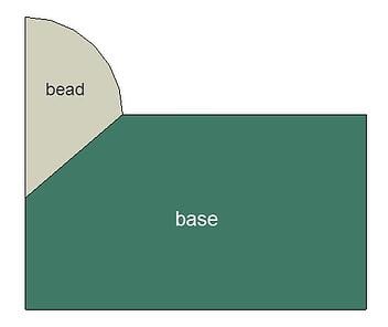
Figure 1: Geometry.
Steps in Thermal Analysis
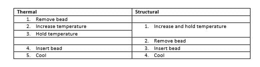
Initially, the bead is removed (step 1). To simulate the torch passing, a thermal boundary condition is then applied to what will be the contact area between the bead and the base (step 2). This temperature is held for a certain amount of time (step 3). The bead is then inserted (step 4), after which the entire construct can cool down (step 5). Therefore, 5 heat transfer steps are created.
Activating/Deactivating Elements Using the Model Change Option
Elements can be added during the analysis using the Model change option. In order to add them later on, they need to be part of the initial geometry and first removed (deactivated). They can then be included (activated) later on.
The steps used to remove or include elements (steps 1 and 4) are chosen to be very short, 1e-7 s. This way, the temperature field will not change noticeably during steps that are only meant to add or remove material.
The model change option can be found in the Interaction module: create an interaction of type ‘Model change’ (Figure 2).
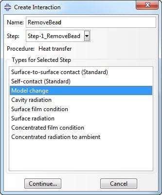
Figure 2: Selecting the Model change option.
The bead is selected as region to be deactivated in step 1 (Figure 3).
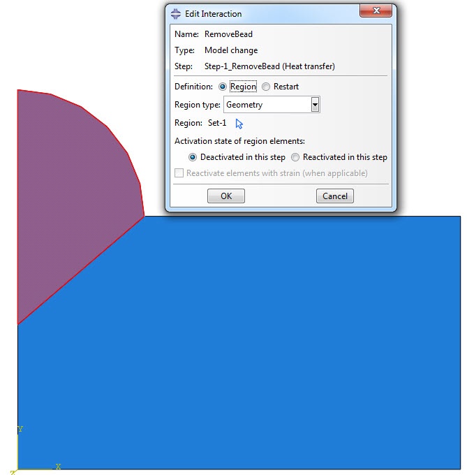
Figure 3: Deactivating the bead region in step 1.
In step 4, the interaction can then be modified, to reactivate the region elements.
Applying Initial Temperature
An initial temperature is prescribed to the geometry using predefined fields. The base material is at room temperature. The bead material is at a high temperature (1500 ̊C) so it will have this temperature when the elements are inserted and the material stiffness in the structural analysis will initially be low.
Applying Boundary Conditions
During the second step, a ramped up temperature boundary condition is applied at the edge between the bead and the base, which is held constant during step 3, and made inactive in step 4.
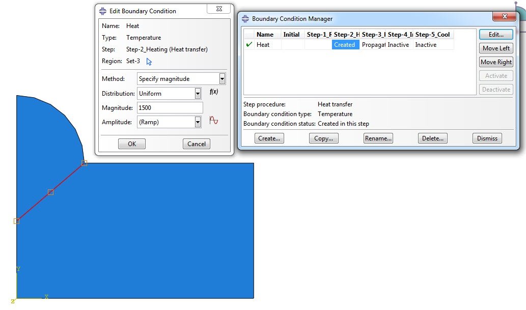 Figure 4: Applying temperature boundary condition.
Applying Film Conditions
Film conditions are applied to the outer edges of the construct. Because the outer edges of the construct change during the simulation, the applied film conditions also change during the simulation (Figure 5). The different regions are all selected manually.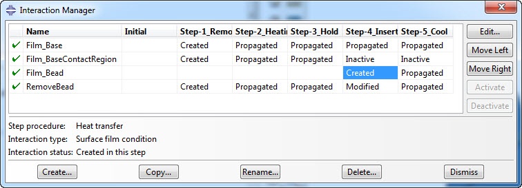
Figure 5: Interaction manager showing applied film conditions in each step.
Output
Temperature output at the nodes is required for the subsequent structural analysis. This is included in the default output.
Thermal Job Submission
When the model is defined, a job can be created and the analysis can be run.
Structural Model
We can then focus on the second model, the structural model. A new model is created in the same model database and the parts, instances, materials and sections are copied using model --> Copy Objects. The elements are changed into structural elements. No further changes to the mesh are made.
Steps in the Structural Model
If the bead material is removed at the start of the analysis and placed back when it is needed, the surrounding material may have displaced in the meantime. If the removed nodes are then replaced to their original position, the elements may be distorted. To avoid this, the material is not removed initially. Instead it is at a high temperature, so the stiffness will be low and it will not significantly influence the rest of the analysis. When bead placement is simulated, the elements are first removed and then placed back without stress or strain. This step division is then as shown in Table 1, so four steps are created.

Table 1: Comparison between step division in thermal and structural model.
Elements are deactivated and activated using the method described for the thermal model.
Applying Temperature Results From Thermal Analysis
The temperature that is calculated in the thermal analysis, is applied to the structural analysis using a predefined field. The predefined field of category ‘other’ and type ‘Temperature’ is created in the first step and the region where the temperature is to be applied is selected. The edit predefined field dialog box (Figure 6) is used to specify which temperature results should be used.
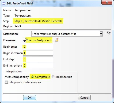
Figure 6: The Edit Predefined Field dialog box, used to prescribe temperature results from a previous analysis.
‘From results or output database file’ is selected as distribution. ‘File name’ is used to refer to the .odb containing the results of the thermal analysis. You can select the step and increment at which to start reading results and also the step and increment at which to stop reading results. Selecting 0 as end increment reads results up to and including the last increment. Since the same mesh is used for the thermal and structural analysis, the mesh compatibility is set to ‘compatible’.
This predefined field needs to be modified in the last step so that it refers to the cooling step in the thermal analysis. Abaqus now has all the information it needs to prescribe the temperature from the thermal analysis in the structural analysis.
When suitable boundary conditions are applied, a job can be created and submitted.
Results
When animating results from both analyses next to each other, it is clear that the temperature from the thermal analysis is indeed applied to the structural analysis (though the time increments were not exactly the same and therefore output is not written at the same points in time).
In the structural analysis, strains develop in the bead initially, but are removed after bead replacement as expected (Figure 7).
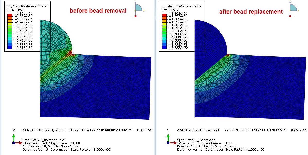
Figure 7: Strains in the model before bead removal and after bead replacement.
Results such as equivalent plastic strain (PEEQ) and von Mises stress are available for the structural model (Figure 8).
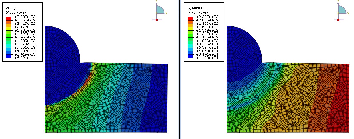
Figure 8: PEEQ (left) and von Mises Stress (right) at the end of the structural analysis.
Conclusion
I have shown an example of setting up a very simple welding simulation. A similar approach could be used for more complex welds involving multiple passes with different beads, possibly in 3D. This requires the definition of many steps, interactions and predefined fields on changing regions in the thermal and structural model. A plug-in has been developed to simply the set-up of more complex welding models: the Abaqus Welding Interface. More on that in a later blog, to be called > Welding simulation using Abaqus - Part 2


TECHNIA Simulation provides top tier FEA, Non-linear, and Advanced Simulation Software, Training, and Consultancy. Our dedicated team of more than 65 Simulation experts across 16 countries advise and support your innovation with a wealth of specialist knowledge and experience.
About TECHNIA- Related news and articles straight to your inbox
- Hints, tips & how-tos
- Thought leadership articles

Helping you find the information you’re looking for. Discover webinars, events, FAQ's, case studies and tutorials.
VIEW HUB